Pin input jack wiring, Rf bypassing, Input jack wiring diagram – Lectrosonics UM400 User Manual
Page 13
Frequency-Agile UHF Belt-Pack Transmitter
5-Pin Input Jack Wiring
The wiring diagrams shown on the next page represent
the basic wiring necessary for the most common types
of microphones and other audio inputs. Some micro
phones may require extra jumpers or a slight variation
on the diagrams shown.
Caution: When wiring the connector, do not
use the connector body for any electrical
connections. A common mistake is to use
the connector body as an audio ground. The
connector body is already used as an RF
ground on VHF models and no other use is
permitted.
It’s virtually impossible to keep completely up to date on
changes that other manufacturers make to their prod
ucts. It is possible that you may encounter a micro
phone that differs from these instructions. If this occurs
please call our toll-free number listed on page 15 of this
instruction manual. Our service department can answer
your questions regarding microphone compatibility.
When used on a wireless transmitter, the microphone
element is in the proximity of the RF coming from the
transmitter. The nature of electret microphones makes
them sensitive to RF, which can cause problems with
the microphone/transmitter compatibility. If the electret
microphone is not designed properly for use with wire
less transmitters, it may be necessary to install a chip
capacitor in the mic capsule or connector to block the
RF from entering the electret capsule. This modification
is shown on the next page.
VHF transmitters use the shield of the microphone
cord as the antenna. This transmitter uses a 1/4 wave
flexible wire to radiate the RF signal. There is really not
much difference between these two approaches, with
respect to the effect of the RF on the microphone cap-
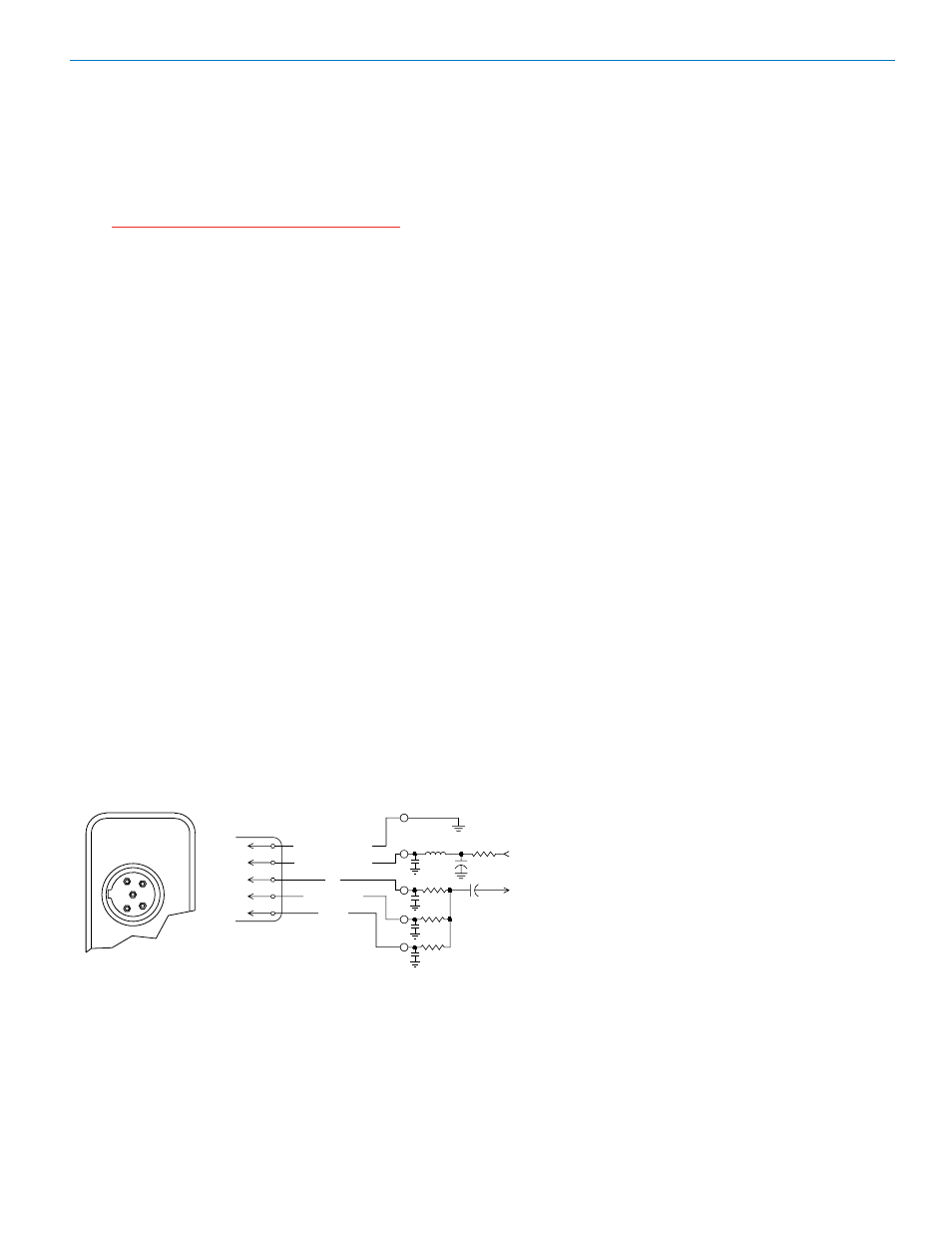
Input Jack Wiring Diagram
FB
40k
4k
5
100
4
3
2
1
+
POS BIAS (OR GND)
MIC
SOURCE LOAD
LINE IN
NEG GND (OR BIAS)
+
1k
10uF
330pF
330pF
330pF
330pF
4
3
2
1
5
LECTROSONICS
TRANSMITTER
INPUT JACK
sule. Even in transmitters that utilize a “dangling wire,”
the microphone is still part of the “ground plane” and is
therefore still in the antenna circuit.
PIN 1 Shield (ground) for positive biased electret
lavaliere microphones. Bias voltage source for
negative biased electret lavaliere microphones.
Shield (ground) for dynamic microphones and
line level inputs.
PIN 2 Shield (ground) for negative biased electret
lavaliere microphones. Bias voltage source for
positive biased electret lavaliere microphones.
PIN 3 Low impedance microphone level input for
dynamic microphones. Also accepts hand-held
electret microphones provided the microphone
has its own built-in battery.
PIN 4 4K Ohm source load for non-Lectrosonics elec
tret microphones. Use in conjunction with other
pins to provide attenuation of high level input
signals.
PIN 5 High impedance, line level input for tape decks,
mixer outputs, musical instruments, etc.
RF Bypassing
Some mics require RF protection to keep the radio
signal from affecting the capsule, even though the
transmitter input circuitry is already RF bypassed (see
schematic diagram).
If the mic is wired as directed, and you are having dif
ficulty with squealing, high noise, or poor frequency
response; RF is likely to be the cause.
5V Mic Bias
To Mic Amp
Rio Rancho, NM
1