Frequency select switches, Input jack, Modulation leds – Lectrosonics UH400a User Manual
Page 7: Input signal level, Input gain adjustment
Frequency Agile Plug-On UHF Transmitter
The transmitter can supply 4 mA at 42 Volts, 8 mA at 15
Volts, and 8 mA at 5 Volts. The 42 Volts setting actually
supplies the same voltage to a 48 Volt microphone as
the DIN standard arrangement due to a dynamic bias
ing scheme that does not have as much voltage drop
as the DIN standard. The 48 Volt DIN standard arrange
ment protects against shorts and high fault current with
high resistance in the power supply feeds to pins 2 and
3. This protects the supply if the supply current is ac
cidentally shorted to ground and also keeps the micro
phone from being attenuated by the power supply. The
UH400A improves on those functions and is able to use
less power from the battery by using constant current
sources and current limiters. With this dynamic arrange
ment the UH400A can also supply more than twice the
current of competing 48 Volt plug on units and provide
four times the current for some very high end 15 Volt
microphones.
The 5 Volt setting is provided for lavaliere microphones
made by us and others. Do not power lavalieres from
the 15 or 48 Volt setting as the microphone will most
likely be destroyed. Lectrosonics makes an adapter,
MCA5X, that will adapt our standard TA5F 5 pin mi
crophones to the UH400A. This adapter also provides
protection against excessive phantom voltage. If volt
ages higher than 5 Volts are applied to the adapter, a
Zener diode will shunt excess voltage to ground. The
microphone won’t work until the voltage is correctly
reduced to 5 Volts. If you have an older lavaliere mic
that was wired directly to an XLR for use with the earlier
UH200’s, we strongly recommend building our protec
tion circuit into the XLR to prevent accidental destruc
tion of the lavaliere.
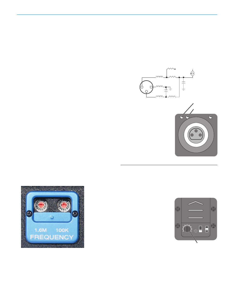
Frequency Select Switches
Two 16 position rotary switches adjust the operating
frequency and are also used for setting Compatibility
Modes.
Left Switch
1.6 MHz
Right Switch
100 kHz
The 1.6 MHz is a coarse adjustment and the 100 kHz is
the fine adjustment. Each transmitter is factory aligned
at the center of its operating range. The default position
of the frequency select switches is in the center of the
transmitter’s range.
Input Jack
Standard 3-pin Switchcraft XLR type with locking collar.
Pin 2 is signal, pin 3 is a floating signal ground, and pin
1 is case ground (see schematic below).
1
2
3
+5V / +18V / +48V
4.7uf
1uh
1uh
1uh
To Mic
Preamp
1000
I
100 pf
511
1000
-20 dB LEVEL
Modulation LEDs
-10 dB LEVEL
The Modulation LEDs
indicate the proper setting
of the MIC LEVEL control.
There are two bicolor modu
lation LEDs that can light
either red or green depend
ing on the amount of gain
applied. The transmitter
should be set so that both
LEDs glow green, with the
-20 LED occasionally blink
ing red.
Signal Level
-20 LED
Less than -20 dB
Off
Off
-20 dB to -10 dB
Green
Off
-10 dB to +0 dB
Green
Green
+0 dB to +10 dB
Red
Green
Greater than +10 dB
Red
Red
Input Signal Level
LEDs on the panel next to
the input coupler display the
modulation level for proper
input gain adjustment.
Input Gain Adjustment
The rotary control on the
recessed panel adjusts the
gain over a 43 dB range to
PHTM
NO PHTM
PWR OFF
LEVEL
5V
15V
48
V
INPUT GAIN ADJUSTMENT
set the proper modulation.
-10 LED
Rio Rancho, NM
7