General technical description, Introduction, Digital hybrid technology – Lectrosonics T4 User Manual
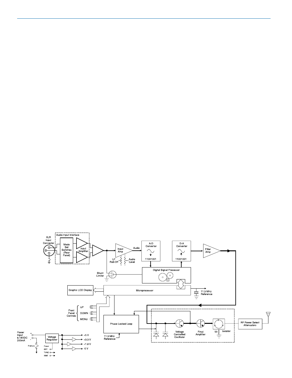
Page 4: Audio input interface, Ifbt4 transmitter block diagram
IFBT4
LECTROSONICS, INC.
4
Introduction
The IFBT4 IFB transmitter brings DSP capability and a
convenient LCD interface to the popular Lectrosonics
IFB product line. Replacing the venerable IFBT1 trans-
mitter, the IFBT4 retains the same physical size and is
fully interchangeable with its predecessor in terms of
audio, RF and power interfaces. The IFBT4 also offers
new features such as selectable LF roll-off and com-
patibility with Lectrosonics 100, 200 and 400 Series
systems as well as some other popular brands.
The IFBT4 features a graphics type backlit LCD display
with a menu system similar to those featured in our 400
Series receivers. The IFBT4 can be “Locked” to prevent
a user from changing any settings but still allow brows-
ing of the current settings.
The IFBT4 can be powered from any external DC
source of 6 to 18 Volts at 200 milliamps maximum or
from the provided 12 Volt power supply with a locking
power connector. The unit has an internal self-resetting
fuse and reverse polarity protection.
The IFBT4 is housed in a machined aluminum case
with a tough electrostatic powder coating. The front and
rear panels are anodized aluminum with laser etched
engraving. The included antenna is a right angle, ¼
wavelength monopole with a BNC connector, construct-
ed of polymer coated flexible steel cable.
These features, along with the 250 milliwatt RF output
and a wide range of selectable audio input types and
levels, make the IFBT4 an excellent choice for long
range IFB applications and other long range wireless
audio needs.
Digital Hybrid Technology
The IFBT4 features Lectrosonics Digital Hybrid Technol-
ogy for full compatibility with all of the Lectrosonics 400
Series and Venue receivers. The Lectrosonics Digital
Hybrid system in the 400 Series mode overcomes
channel noise and compandor artifacts in a dramatically
new way, digitally encoding the audio in the transmitter
and decoding it in the receiver, yet still sending the en-
coded information via an analog FM wireless link. This
proprietary algorithm is not a digital implementation of
an analog compandor but a technique which can be ac-
complished only in the digital domain. As of this writing,
the patent is still pending.
Audio Input Interface
The standard 3 pin XLR connector on the rear panel
handles all audio inputs. The four DIP switches allow
setting the input sensitivity for low levels, such as micro-
phone inputs, or for high levels, such as line inputs, bal-
anced or unbalanced. The switches also offer special
settings to provide the proper input configurations to
match to Clear Com, RTS1, and RTS2 intercom sys-
tems. Pin 1 of the XLR input connector is normally con-
nected to ground but an internal jumper can be moved if
a floating input is desired.
While the XLR input does not offer phantom power, it is
fully compatible with standard 48 Volt phantom power.
Phantom supplied microphones may be connected to
the IFBT4 without the need for DC isolation.
General Technical Description
IFBT4 Transmitter Block Diagram