Installation and operation – Lectrosonics T4 User Manual
Page 10
IFBT4
LECTROSONICS, INC.
10
The AUDIO LEVEL control should not be used to
control the volume of the associated receiver. This gain
adjustment is used to match the IFBT4 input level to the
incoming signal from the sound source to provide full
modulation and maximum dynamic range, not to set the
volume of the associated receiver.
If the audio level is too high — the audio metering
will exceed the 0 dB level too frequently. This condi-
tion may reduce the dynamic range of the audio
signal.
If the audio level is too low — the audio metering
will be too far below the 0 dB level. This condition
may cause hiss and noise in the audio, or pumping
and breathing in the background noise.
The input limiter will handle peaks over 15 dB above full
modulation, regardless of the gain control setting. Oc-
casional limiting is often deemed desirable, indicating
that the gain is correctly set and the transmitter is fully
modulated for optimum signal to noise ratio. Different
voices will usually require different audio input gain
settings, so check this adjustment as each new person
uses the system. If several different people will be using
the transmitter and there is not time to make the adjust-
ment for each individual, adjust it for the loudest voice.
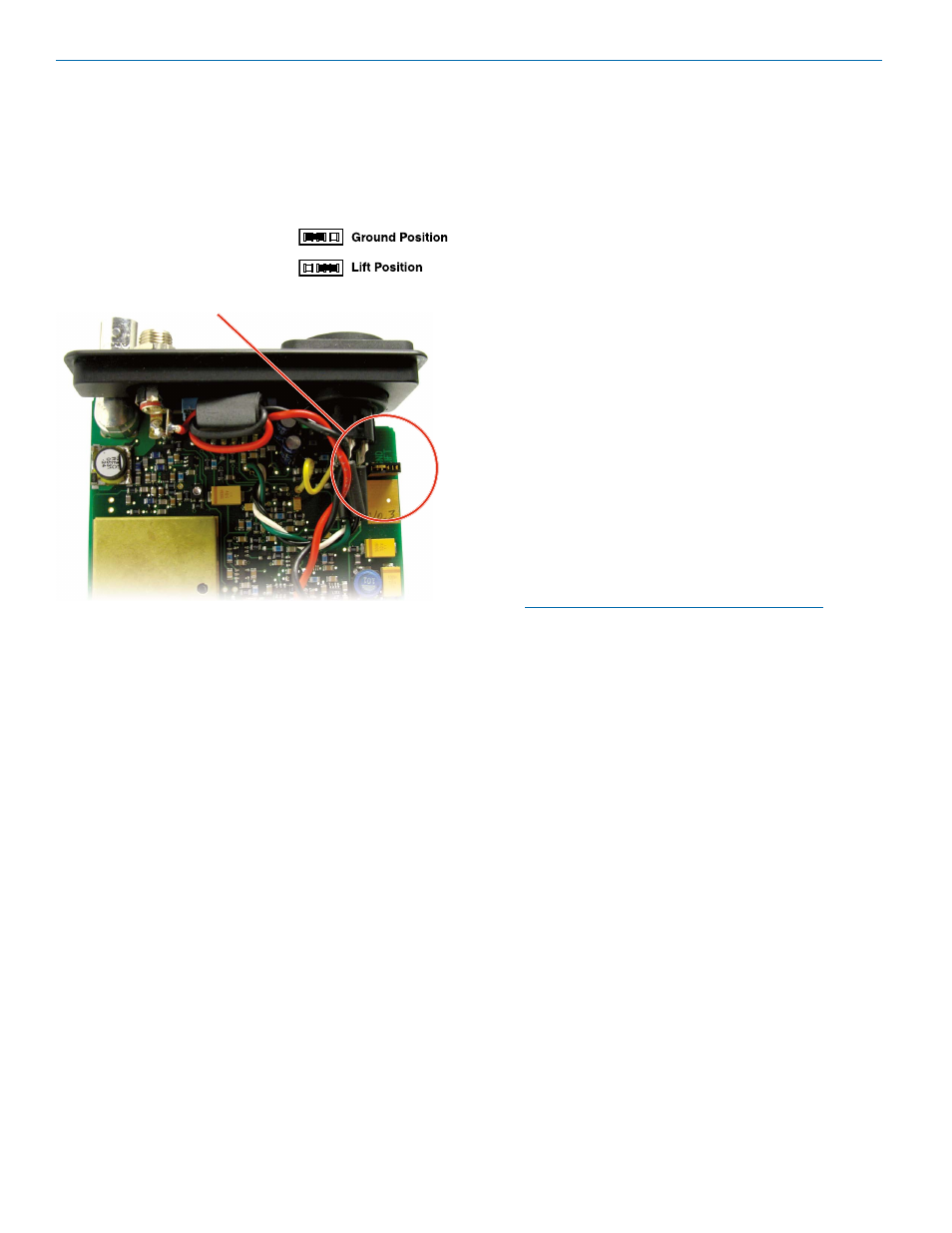
1) The IFBT4 transmitter is shipped with pin 1 of the
XLR input connector tied directly to ground. If a
floating input is desired, a Ground Lift Jumper is
provided. This jumper is located inside the unit on
the PC board near the rear panel XLR jack. For
floating input, open the
unit and move the Ground
Lift Jumper to the desired
location.
Installation and Operation
4) Insert the microphone or other audio source XLR
plug into the input jack. Ensure that the pins are
aligned and that the connector locks into place.
5) Attach the antenna (or antenna cable) to the BNC
connector on the rear panel.
6) Set the OFF/TUNE/XMIT switch to TUNE.
7) Press the MENU button to display the Frequency
Window and adjust the transmitter to the desired
frequency with the front panel Up and Down but-
tons.
8) Position the microphone. The microphone should
be placed where it will be located during actual use.
9) Use the MENU button to navigate to the Audio Input
Gain Window. While speaking at the same voice
level that will be present during actual use, observe
the audio meter display. Use the Up and Down but-
tons to adjust the audio input gain so that the meter
reads close to 0 dB, but only rarely exceeds 0 dB
(limiting).
10) Once the transmitter audio gain has been set, the
receiver and other components of the system can
be turned on and their audio levels adjusted. Set
the power switch on the IFBT4 transmitter to XMIT
and adjust the associated receiver and sound sys-
tem level as required.
Note: There will be a delay between the moment
the transmitter is energized and the actual
appearance of audio at the receiver output. This
intentional delay eliminates turn-on thumps, and is
controlled by the pilot tone squelch system.
Location of Ground Lift Jumper:
2) Set the MODE switches on the rear panel to match
the specific input source to be used. (See MODE
Switches.)
3) Insert the power supply plug into the 6-18 VDC jack
on the rear panel.
Operating Notes