General technical description, Rf frequency tracking front-end and mixer, Microcontroller, pll and vco circuits – Lectrosonics UCR511 User Manual
Page 5: If amplifiers and saw filters, Compatibility modes, Diversity reception, The ucr511 technology with smart diversity, Uhf wireless digital hybrid, Receiver, Rio rancho, nm – usa
UHF Wireless Digital Hybrid
TM
Receiver
GENERAL TECHNICAL DESCRIPTION
The UCR511 is a portable, high performance, triple-
conversion, frequency synthesized, UHF receiver fully
compatible with all Lectrosonics 500 series transmitters
(and some other transmitter types – see Compatibility
Modes for details.) The RF performance is extremely
stable over a very wide temperature range, making the
UCR511 perfectly suited to the rough environmental
conditions found in the field. The proprietary audio
processing includes a digital signal processor for very
low distortion and a superior signal to noise ratio.
The UCR511 features a menu-driven LCD graphic
display and three control buttons to conveniently view
and alter user settings. The main window, for example,
displays the pilot tone indicator, antenna diversity phase,
RF level, audio level, receiver battery status and trans
mitter battery status. It is also possible to bypass the
pilot tone/squelch from the main display window. Other
display windows show operating frequency, audio output
level, battery voltage and test tone status. The fre
quency scan mode provides a spectrum analyzer for a
graphical means of observing all signals “on the air”
within the frequency range of the receiver in order to find
operating frequencies that are free of interference.
COMPATIBILITY MODES
The UCR511 receiver was designed to operate with
Lectrosonics 500 Series transmitters and will yield the
best performance when doing so. However, due to the
flexibility of digital signal processing, the UCR511 is also
able to operate with Lectrosonics 300 Series, Lectroson
ics 100 Series, and certain non-Lectrosonics transmitters
in special compatibility modes.
DIVERSITY RECEPTION
The UCR511 technology with SMART Diversity
™
mini
mizes dropouts in situations where multi-path reflections
can cause serious problems. The phase diversity
network and PIN diode RF switches are controlled by the
microprocessor using a sophisticated algorithm to use
both antennas simultaneously. This design keeps the
receiver compact enough for camera mounting or
shoulder bag applications, yet provides effective diversity
reception.
RF FREQUENCY TRACKING FRONT-END
AND MIXER
The receiver is frequency agile and can be set to operate
on any one of 256 frequencies within its tuning range. To
significantly reduce unwanted interference and inter-
modulation problems, the UCR511 has a frequency
selective front-end section that tracks and tunes to the
desired signal frequency and rejects or “tunes out”
unwanted interfering signals. The design consists of four
varactor tuned ceramic transmission line resonators
controlled by the microprocessor to provide excellent
selectivity. The low noise high current RF amplifier was
designed with feedback regulation for stability and
precise gain in order to handle stronger RF signals
without output overload. The first mixer is of new GaAs
technology that has a very high third order intercept
point. This produces a robust front-end that is as selec
tive as fixed single frequency designs and is suitable for
use in close proximity to other receivers and transmitters
commonly used in field production “bag” systems.
MICROCONTROLLER, PLL AND VCO
CIRCUITS
The 8-bit microprocessor is truly the “heart” of the
UCR511 receiver. It monitors user command inputs from
the front panel control buttons and numerous other
internal signals such as RF level, audio levels, pilot tone
levels and external/internal power voltages. Outputs
from the microcontroller drive the LCD display and
backlight, control the squelch and audio output attenua
tor, and operate the front-end tuning, the PLL/VCO
circuits and the antenna phase switch. The UCR511
design and the advanced technology of the microproces
sor control arguably set a new standard in wireless
microphone development.
IF AMPLIFIERS AND SAW FILTERS
The first IF low noise amplifier is controlled with feed
back regulation and drives the first of two quartz SAW
50
50
5K
5K
uP
LCD
Display
Panel
PILOT TONE
DETECT
FILTER
FILTER
uP uP
DIGITAL SIGNAL
PROCESSOR
Attenuation
CERAMIC
FILTER
2ND
MIXER
10.7 MHZ
SAW
FILTER
244 MHz
IF AMP
A-D
CONVERTER
D-A
CONVERTER
AMP
2nd
VCO
XLR
OUT
HI-LEVEL
MIXER
RF MODULE
3RD MIXER
AND
IF AMP
50KHz
LP FILTER
XTAL
CONTROLLED
3rd
OSCILLATOR
SAW
FILTER
244 MHz
IF AMP
COUNTING
DETECTOR
AUDIO
AMP
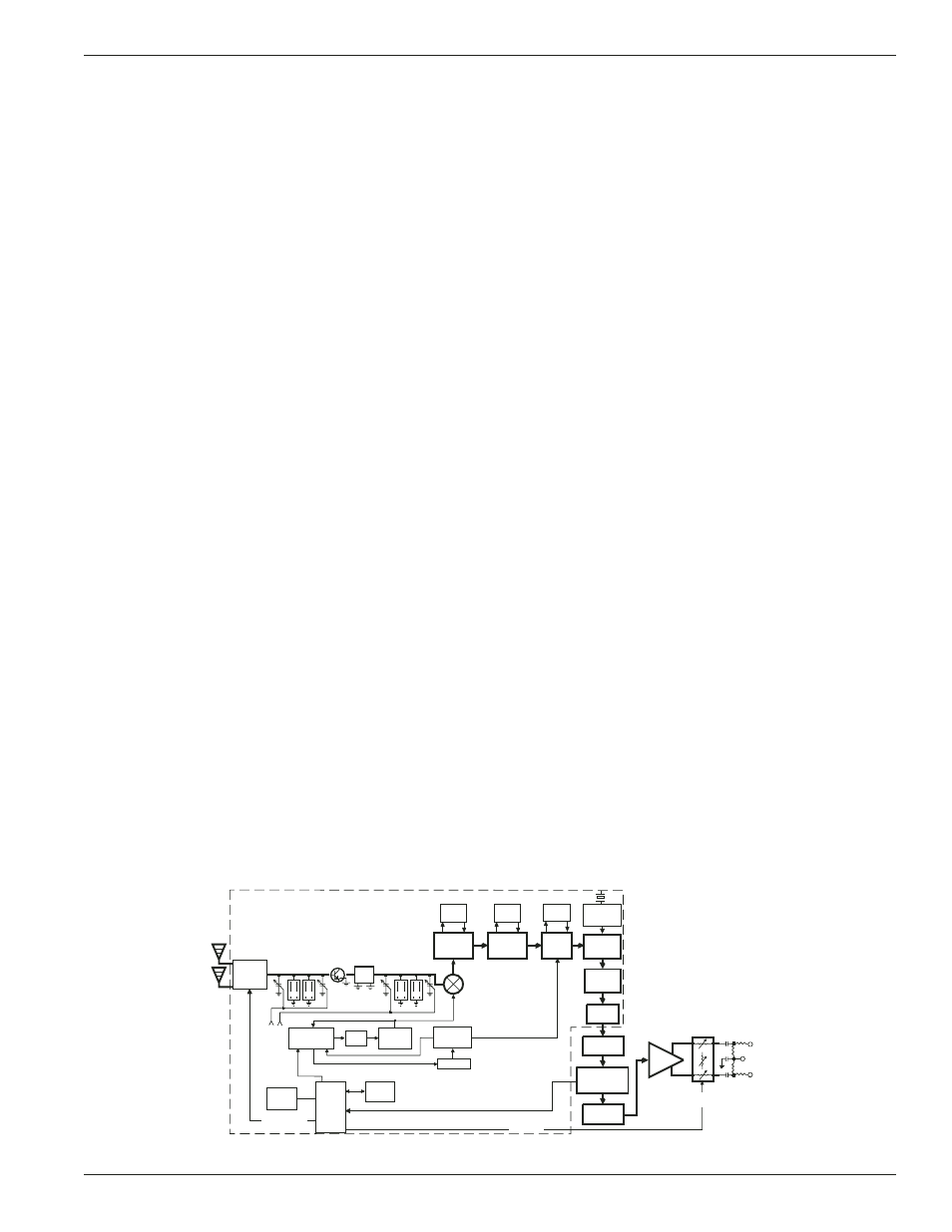
UCR511
BLOCK DIAGRAM
ANTENNA
COMBINING
FILTER
E PROM
2
1st
VCO
Smart Diversity
FILTER
PLL
SYNTHESIZER
LC
Filter
Output
Level
Adjust
Digital
Attenuator
2 (HI)
1 (COMMON)
3 (LO)
Rio Rancho, NM – USA
5