Frequency scan mode, Scan & view window elements, Fine view window elements – Lectrosonics UCR511 User Manual
Page 13
UHF Wireless Digital Hybrid
TM
Receiver
FREQUENCY SCAN MODE
B8
Scan
View
Fine View
Press All 3 Buttons
B8
P
re
s
s
A
ny
Bu
tton
Press Menu
Pr
es
s
M
e
n
u
B8
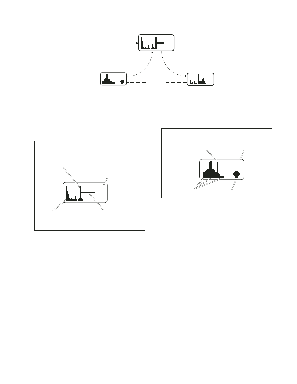
To use the integrated scanning function, press both UP/
DOWN buttons and the MENU button at the same time.
The display will switch to the SCAN WINDOW and start
scanning immediately. Data gathered during a scan is
stored until it is purposely erased or the power is turned
off. Previous data will remain and subsequent scans can
be made to search for additional signals or to accumu
late higher peaks.
Scan & VIEW WINDOW Elements
Cursor - shows relative
Switch Settings - shows
position of the scanner
the transmitter switch
within the 25Mhz band of
settings - will change
the receiver.
rapidly while the unit is
scanning.
Scan level indications
B8
-
Remaining unscanned
showing relative level of RF
part of band.
activity across the 25MHz
bandwidth of the receiver.
To stop scanning, press the MENU button once. The
scanning will stop immediately, and the display will
switch to the VIEW window. In this window, each vertical
band of the display represents eight frequencies (800
kHz). Pressing the SEL Up or Down buttons will scroll
the cursor coarsely across the tuning range. The trans
mitter switch settings matching the frequency indicated
by the cursor are shown in the upper right corner of the
screen.
Spectrum data is collected only when the receiver is
scanning. Successive scanning with repeated passes
through the tuning range will accumulate the highest
peaks encountered to aid in finding clear frequencies. To
clear the scan memory without leaving scan mode, turn
the power switch off and back on quickly.
Pressing the MENU button once will shift the display to
the FINE VIEW window which will show an expanded
portion of the spectrum around the cursor.
In the FINE VIEW window, each vertical band represents
one frequency the UCR511 is capable of tuning. The
upper right corner shows the transmitter switch settings
for the frequency indicated by the cursor. In this screen,
a vertical center bar is the cursor. Underneath the switch
settings are two arrows to remind you that this is a
partial picture of the spectrum and that you can scroll left
or right to view the entire spectrum of the receiver by
pressing the SEL Up or Down buttons.
Fine VIEW WINDOW Elements
Transmitter
Switch Settings
Cursor (center bar)
B8
RF Level indicators
SCROLL reminders
Pressing the SEL Up button will make the display scroll
left, showing higher frequencies. Pressing the SEL
Down button will make the display scroll right, showing
lower frequencies. The cursor remains in place while the
display scrolls left or right
In addition to assessing the congestion within the RF
tuning range of the receiver, the scanning mode is also
used to find a clear operating frequency. Scroll through
the screen and find a frequency where no RF signals are
present (or in the worst case, only very weak RF sig
nals). With the cursor on this frequency, press the SEL
Up, SEL Down and MENU buttons at the same time to
leave the scan mode.
When leaving the scan mode, you are given the option of
using the frequency the unit was on before entering the
scan mode, or using the frequency just selected in the
scan mode. The display shows USE OLD and USE
NEW to prompt you to make a frequency selection. To
accept the new frequency just selected in the scan
mode, press the DOWN button for USE NEW. To return
to the frequency you were using before entering the scan
mode, press the UP button for USE OLD. (The MENU
button defaults to USE OLD).
Once you leave the scan mode, the Frequency Window
will be displayed. Set your transmitter switches to the
same settings as shown on the display and your system
will be ready for operation.
Rio Rancho, NM – USA
13