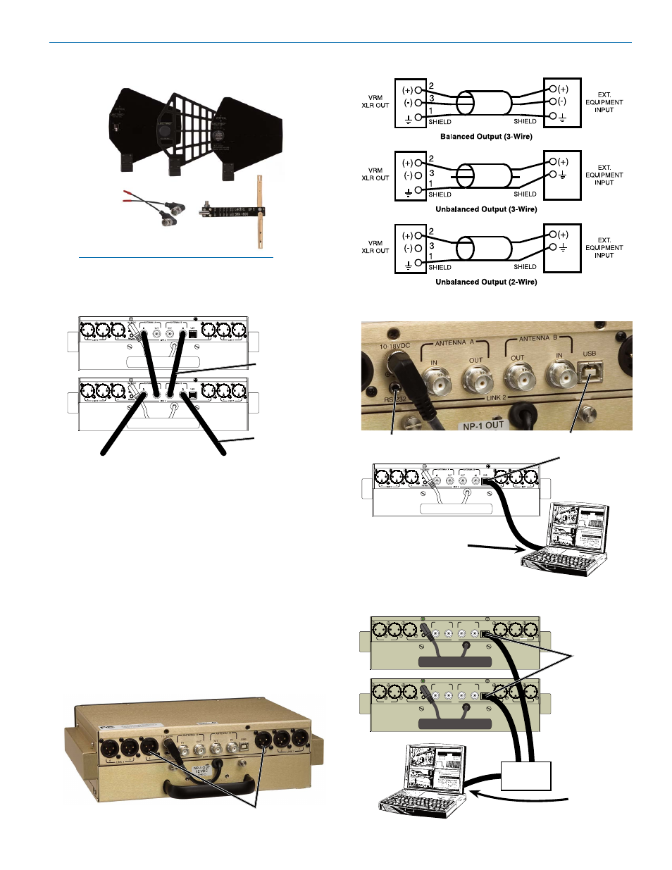
Typical usb hookup for single vr field system, Typical usb hookup for multiple vr field systems, Audio output wiring diagrams – Lectrosonics VR Field (Wideband) User Manual
Page 9: Usb hub, Usb port on computer system
Digital Hybrid Wireless™ Modular Receiver System
Rio Rancho, NM, USA
9
ALP Series
A500RA
SNA600
USB Port on
Computer System
Typical USB Hookup for Single VR Field System
NOTE: Frequencies of the receiver modules
must be within the range of whip antennas and
the SNA600 dipole. The ALP Series antennas are
wideband designs that cover the entire range.
4. Insert a charged battery into the front panel, or plug
the VR Field power supply into a suitable outlet
and plug the power connector into the Power Input
Jack (unscrew the power connector that goes to the
battery). Repeat for each VR Field System being
installed.
5. Turn down the audio inputs on all the externally
connected equipment, then connect them to the ap-
propriate Audio Output XLR Jacks.
6. If the VR Field System is to be set up using a com-
puter system using a USB interface, connect a USB
cable between the USB connector on the rear panel
of the VRF and the computer system or a USB hub
connected to the computer system.
7. Refer to “Setting Up the VR Field System via the
USB Port”.
USB Port on
Computer
System
Typical USB Hookup for Multiple VR Field Systems
USB Port
on VR FIeld
System Rear
Panel
Typical Lectrosonics
Antenna Combinations
Coaxial
Patch Cables
(Not Supplied)
Antenna Inputs
10-18VDC
RS-232
6
5
4
LINK 2
3
2
1
IN
USB
IN
OUT
OUT
ANTENNA A
ANTENNA B
LINK 1
LINK 3
1
2
3
1
2
3
1
2
3
1
2
3
1
2
3
1
2
3
10-18VDC
RS-232
6
5
4
LINK 2
3
2
1
IN
USB
IN
OUT
OUT
ANTENNA A
ANTENNA B
LINK 1
LINK 3
1
2
3
1
2
3
1
2
3
1
2
3
1
2
3
1
2
3
USB Hub
RS-232 Port
USB Port on VR Field
System Rear Panel
Audio Output XLR Jacks
Audio Output Wiring Diagrams