Adjusting audio output levels – Lectrosonics VR Field (Wideband) User Manual
Page 16
VR Field Wideband Receiver
LECTROSONICS, INC.
16
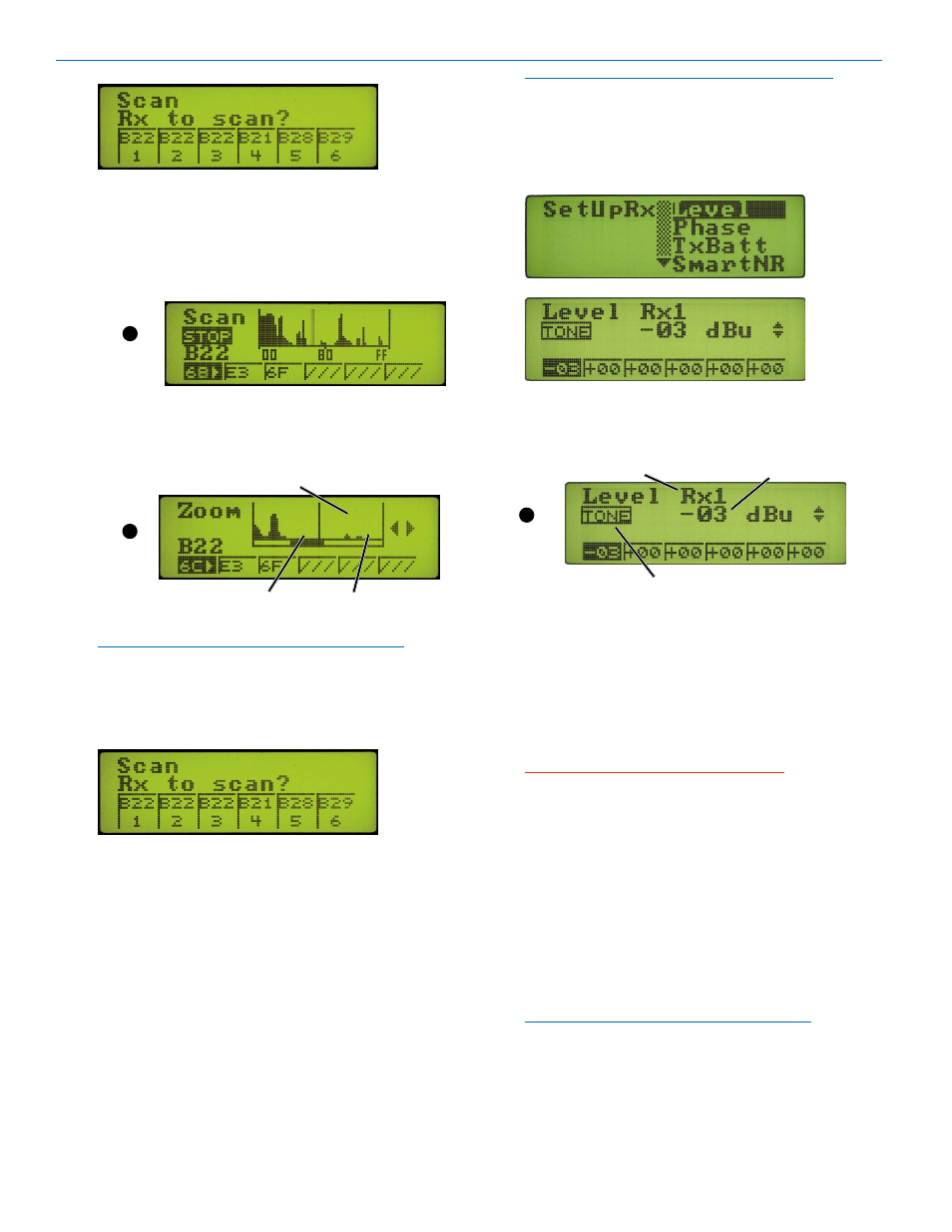
Select the receiver module to use for scanning and
press MENU/SELECT. The scanning begins auto-
matically.
3. Allow the scanner to continue sweeping through the
tuning range several times, then press the Function
button to enter “Stop Mode.”
Function
Button
4. With the scanning stopped, rotate the MENU/
SELECT control to adjust the frequency to clear
spectrum. Press the Function Button to ZOOM to a
close up view of the scan results.
Function
Button
Cursor blinks
Strong Interference
Clear Spectrum
5. Press the BACK button to return to the “Stop Mode.”
NOTE: At any point in the Stop or Zoom screens,
you can select any module on the same block to
tune.
6. Press the BACK button to return the previous menu
to select the next receiver to use for scanning.
7 . Continue from step 2 to scan all blocks that are
installed.
8. Conduct a system checkout with the procedure
explained in the section entitled Diagnostics.
Adjusting Audio Output Levels
The audio output levels at the rear panel XLR jacks are
software controlled. (The front panel LEVEL knob af-
fects the PHONES output only.)
The optimum output level will provide the highest level
signal possible without overloading the input to external
equipment or driving a subsequent stage in the signal
chain into limiting or compression. Ideally, the gain
needed to drive the rest of the signal chain should be
present at the receiver outputs, with each successive
stage in other equipment set to unity (no gain or loss).
NOTE: In Ratio Diversity and Frequency Diversity
modes, the receiver modules are paired 1-2, 3-4,
5-6. Setting the audio level output on either module
in the pair, sets the audio output to the same level
on both of them.
1. Navigate to the Level setup screen.
2. Select each receiver one at a time with the buttons
under the LCD and rotate the knob to adjust the
output to the desired level.
Selected Receiver
Output Level
Tone On/Off Indicator
(Shown in Off position.)
Function
Button
3. Use the Tone Generator to adjust other equipment
to match the output level from the receiver with full
modulation of the transmitter. Press the Function
Button to start the tone.
The indicator will reverse to a dark background
with light letters when the tone is delivered to the
selected output. Rotate the MENU/SELECT control
to set the desired level.
WARNING: The 1 kHz reference tone is
equivalent to full modulation at the transmitter.
It is LOUD.
The test tone level is always at the 0dB reference level
(full modulation of the wireless system), which is the
level at which the first red “limit” light comes on at the
transmitter.
The highest level that the equipment downstream will
ever see before the receiver clips is 4.5 dB higher than
the test tone. Note that this is
output headroom. Over
the entire 30+ dB range of the limiter in a Lectrosonics
transmitter, the output at the receiver goes up only 4.5
dB or less.
NOTE: The tone is a sine wave with about 1%
distortion