Transmitter aes3 modes, Receiver aes3 modes, Mixed modes – Lectrosonics D4 System User Manual
Page 12: Connector pinouts
D4T/D4R
LECTROSONICS, INC.
12
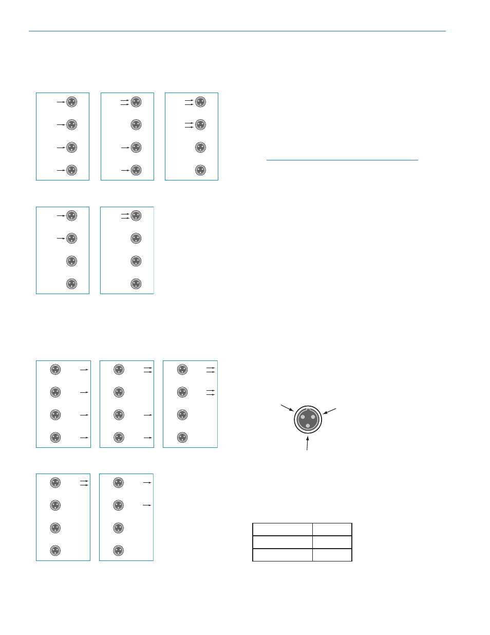
Transmitter AES3 Modes
The transmitter can be set up in three different con-
figurations with the AES3 modes menu for 4-channel
operation:
ANALOG
ANALOG
ANALOG
ANALOG
DIGITAL
DIGITAL
ANALOG
ANALOG
NOT USED
CH 1
DIGITAL
DIGITAL
NOT USED
NOT USED
CH 2
DIGITAL
DIGITAL
CH 3
CH 4
CH 1
CH 2
CH 3
CH 4
CH 1
CH 2
CH 3
CH 4
Two different configurations are available for 2-channel
operation:
ANALOG
ANALOG
DIGITAL
DIGITAL
NOT USED
NOT USED
NOT USED
NOT USED
NOT USED
CH 1
CH 2
CH 3
CH 4
CH 1
CH 2
CH 3
CH 4
Receiver AES3 Modes
The receiver audio outputs can be configured in the
same manner as the transmitter for 4-channel opera-
tion:
ANALOG
ANALOG
ANALOG
ANALOG
DIGITAL
DIGITAL
ANALOG
ANALOG
NOT USED
DIGITAL
DIGITAL
NOT USED
NOT USED
DIGITAL
DIGITAL
CH 1
CH 2
CH 3
CH 4
CH 1
CH 2
CH 3
CH 4
CH 1
CH 2
CH 3
CH 4
Two different configurations are available for 2-channel
operation:
DIGITAL
DIGITAL
NOT USED
NOT USED
NOT USED
ANALOG
ANALOG
NOT USED
NOT USED
CH 1
CH 2
CH 3
CH 4
CH 1
CH 2
CH 3
CH 4
Mixed Modes
The selected AES3 modes on the transmitter and re-
ceiver do not have to be identical. For example, analog
signals can be fed into the transmitter from a mixer or
wireless mic receivers, transmitted to the D4R receiver,
which can be configured for four digital outputs to feed
a digital recorder.
The sampling rate of the audio at the receiver digital
outputs will always be 48 kHz, regardless of the sam-
pling rate of the signal fed into the transmitter.
NOTE: Transmitter and receiver must be set for
the same number of audio channels.
Connector Pinouts
TA3M (3-pin male) panel mount connectors are used
on the transmitter and receiver because they are
smaller than the flange mounted female jacks, and to
allow the use of right angle connectors such as the
RATPAC. The same pin numbering as XLR jacks is
used for AES-EBU and analog audio devices.
Digital Signals – two audio channels per jack:
Pin 1:
Shield (ground)
Pin 2:
Signal
Pin 3:
Signal
Analog Signals – one audio channel per jack:
Pin 1:
Shield (ground)
Pin 2:
Audio (+)
Pin 3:
Audio (–)
When looking at the rear panel of the transmitter and
receiver, the pins in the TA3M jack are numbered in
this pattern:
Pin 2
Pin 1
Pin 3
Polarity of pins 2 and 3 is not important in the digital
domain, but it is generally good practice to maintain
the pin to pin connections shown below when adapting
to standard XLR connectors. Adapter cables wired this
way can be used for both digital and analog signals.
TA3M
XLR
Pin 1
Pin 1
Pin 2
Pin 2
Pin 3
Pin 3