Specifications, Lv 7380 – LEADER LV7380 User Manual
Page 2
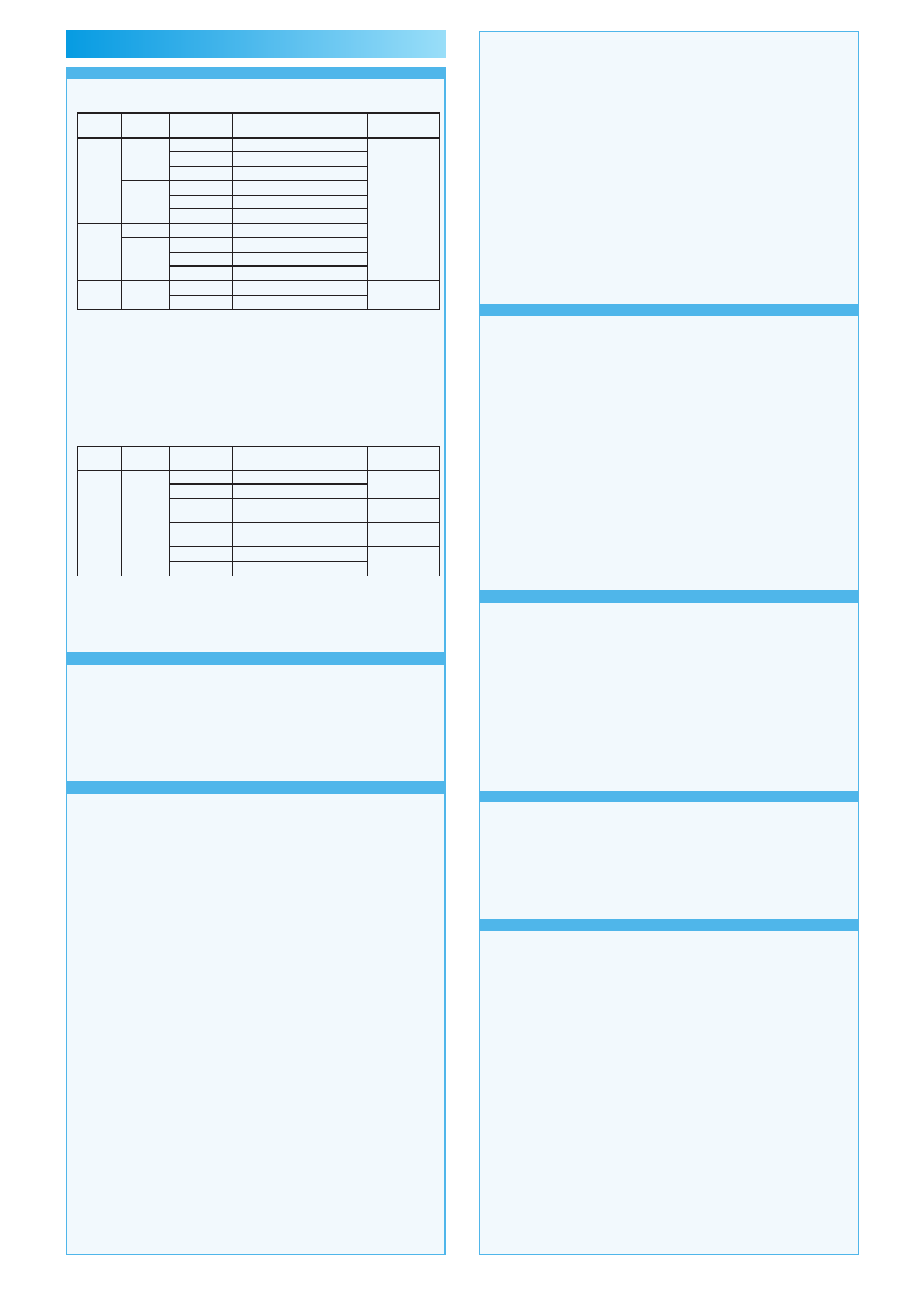
Video Signal Formats and Standards
Supported Formats of Dual Link System Video Signals and
Corresponding Standards
Color
System
Quantization
Scanning
Frame (Field) Rates
Corresponding
Standard
GBR
4:4:4
10 bit
1080p
30/29.97/25/24/23.98
SMPTE 372M
(1920 × 1080)
1080PsF
30/29.97/25/24/23.98
1080i
60/59.94/50
12 bit
1080p
30/29.97/25/24/23.98
1080PsF
30/29.97/25/24/23.98
1080i
60/59.94/50
Y, C
B
, C
R
4:2:2
10 bit
1080p
60/59.94/50
12 bit
1080p
30/29.97/25/24/23.98
1080PsF
30/29.97/25/24/23.98
1080i
60/59.94/50
GBR 4:4:4
(2K)
12 bit
1080p
24/23.98
(2048 × 1080)
1080PsF
24/23.98
* The picture display bit depth is 8 bits.
When these signals are displayed, phase differences of up to 100
clocks (approx. 1.4 μs) between links A and B are automatically
corrected.
If links A and B are not synchronized, the various error detection
features that are shown on the status display do not operate
correctly.
Supported Formats of Single Link System Video Signals and
Corresponding Standards
Color
System
Quantization
Scanning
Frame (Field) Rates
Corresponding
Standards
Y, C
B
, C
R
4:2:2
10 bit
1080i
60/59.94/50
SMPTE 274M
SMPTE 292M
1080p
30/29.97/25/24/23.98
1080PsF
30/29.97/25/24/23.98
SMPTE RP 211
SMPTE 292M
720p
60/59.94/50/
30/29.97/25/24/23.98
SMPTE 296M
SMPTE 292M
525i
59.94
SMPTE 259M
625i
50
Format Settings
Link Format Switching:
Manually switched between single and
dual link
Format
Setting:
Manual switching. Only frame and field
rates can be set automatically.
Audio Playback
Compliant Standards: SMPTE-299M (HD-SDI) and SMPTE-
272M (SD-SDI)
Quantization: 24
bit
Clock
Generation:
Generated from the video clock
Synchronization:
All audio channels must be synchronized
to the video clock.
Channel Separation:
2 groups (from the same SDI input signal)
of 8 channels are selectable.
Input/Output Connectors
SDI Input
Input
Connectors:
Two BNC connectors
2 inputs in single link mode (channels A
and B)
1 input (link A and B) in dual link mode
Input
Impedance: 75
Ω
Input Return Loss:
≥ 15 dB for 5 MHz to the serial clock fre-
quency
Maximum Input Voltage:
±2 V (DC + peak AC)
SDI Output
Output
Connectors: Two BNC connectors
Reclocks and transmits the input signal
1 output (switchable between channels A
and B) in single link mode
1 output fixed to channel B
1 output (link A and B) in dual link mode
Output
Impedance: 75
Ω
Output
Voltage:
800 mVp-p ± 10 %
External Reference Input
Input
Signal:
Tri-level sync or NTSC/PAL black burst
signal
Input
Connectors:
1 pair of BNC connectors
Maximum Input Voltage: ±5 V (DC + peak AC)
* If the video signal waveform is displayed using an external sync
signal as a reference, the waveform phase one clock before
or after an SDI signal is inserted or the power is turned on is
indefinite.
* External synchronization cannot be used for 1080p/60, 59.94, 50.
Audio Input/Output Connectors
Input/Output:
4 BNC connectors (8 channels)
Supported
Format: AES/EBU
Sampling
Frequency: Only 48 kHz is supported.
Input/Output Switching: Use the menu to select whether the con-
nectors are used as AES/EBU input con-
nectors or as AES/EBU output connectors
that are separated from the SDI signal.
Headphone Output
Output
Signal:
Separate any two channels of audio sig-
nals that are embedded in the SDI signal
and output them (in sync with the video
signal) or output the audio that is being re-
ceived through the audio input connector.
Output
Connector:
One stereo jack
Volume
Adjustment: VOLUME knob
DVI-I Connector
Signal
Format:
Single-link TMDS, analog RGB
Display
Format:
XGA. The effective resolution is 1024 ×
768.
DDC: Not
supported
HOT PLUG Detection:
Not supported
Output
Connector:
One DVI-I connector
Control Connectors
USB Port
Specification: USB
2.0
Media:
Only USB memory devices are supported.
Function:
Used to save screen captures, event logs,
preset data, and data dumps
Ethernet Port
Compliant
Standard: IEEE802.3
Supported
Protocols: TELNET, FTP, SNMP
Input/Output: RJ-45
Function:
Used to control the LV 7380 from a PC
and monitor errors and other events
Type: 10Base-T/100Base-TX
Remote-Control Connector
Function:
Used to recall preset settings, display tally
indications, switch input channels (A or B),
and transmit the alarm signal.
Control
Signal:
LV-TTL level (low active)
Input Voltage Range: DC to 5 V
Control
Connector: 25-pin D-sub (female)
Screen Capture
Function:
Captures the screen
Display:
Displays the captured image or superim-
poses the captured image over the input
signal
Media:
Internal memory (RAM) and USB memory
Only one screen capture can be stored in
the internal memory.
Data Output:
Screen captures can be saved as bitmap
files to USB memory, or they can be
saved in a file format that the LV 7380 can
load.
Data Input:
Data saved to USB memory can be load-
ed and displayed on the LV 7380.
Preset Settings
Number of Presets: 30
Display mode presets: Five for each display mode
Recall Method:
Front panel, remote connector, or Ether-
net command
* The number of presets recalled from the remote connector can
be switched between 8 and 30 (all presets are recalled at once).
Copying:
Preset configurations can be copied as a
group to or from USB memory.
Display Format
Display Format:
XGA. The effective resolution is 1024 ×
768.
In 16:9 and 16:10 modes, the LV 7380
can be displayed on 16:9 and 16:10 LCD
panels (respectively).
* The LCD panel must have a resolution conversion feature.
1 Screen Display:
Waveform, vector, picture, audio, and sta-
tus displays
Multi Screen Display: Waveform and picture; waveform, picture,
and vector; and waveform, picture, vector,
and audio displays
4 Screen Display:
Waveform, picture, vector, audio, status,
and eye pattern (optional) modes can be
selected for each of the four areas of the
display
2-Channel Simultaneous Display: Waveform and picture display and wave-
form and vector display
Thumbnail Display:
Picture, audio level meter, and waveform
displays
Displays can be turned ON and OFF.
* Waveform thumbnails can only be displayed in picture mode.
SPECIFICATIONS
LV 7380