LEADER LV 58SER06 User Manual
Features, Plug-in unit, Lv 58ser06 mpeg decoder specifications
33
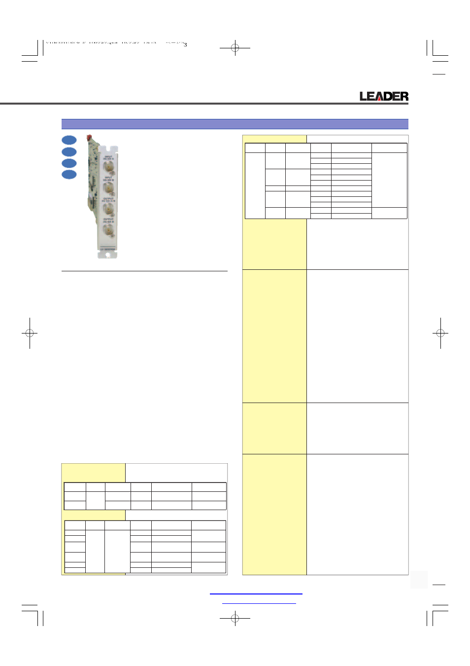
LV 58SER06 3G-SDI INPUT (3G-SDI, HD-SDI, SD-SDI, HD-SDI, DUAL)
Plug-In Unit
This 3G-SDI input unit can be installed
into an input slot of an LV 5800 (multi
monitor) or into an LV 7800 (multi ras-
terizer).
The LV 58SER06 supports 3G-SDI
levels A and B, and it can be used to
display information such as 3G-SDI
signals' video waveforms, vector
waveforms, pictures, and error detec-
tion results on an LV 5800 or LV 7800.
Additionally, by combining the LV
58SER06 with the LV 58SER40A, you
can display information such as the
Lissajous curves and level meters of
embedded audio signals.
What's more, the LV 58SER06 can
generate 3G-SDI signals and test pat-
terns.
FEATURES
• 2 Serial Digital Inputs
The LV 58SER06 has two switchable 3G-SDI input connectors for
monitoring.
• 2 Serial Digital Outputs
The LV 58SER06 can reclock input signals that are received by the
input terminal that has been selected with the input key (3G-SDI A
or 3G-SDI B) and generate these reclocked signals from the 3G-SDI
A/B output connector.
From the 3G-SDI B output connector, the LV 5800 can transmit a
reclocked signal from the 3G-SDI signal that is received through the
3G-SDI B input connector.
• Test Pattern Signal Outputs
The LV 58SER06 can operate as a 3G-SDI signal pattern generator
to generate a 3G-SDI signal from the two output terminals.
• Video Signal Display
The LV 58SER06 can be used to display 3G-SDI signals' video sig-
nal waveforms, vector waveforms, and pictures on not only the 1-
screen display, but 2- and 4-screen multi displays.
• Error Detection
The LV 58SER01A can detect CRC and other 3G-SDI signal errors
that are related to embedded audio signals and ancillary data.
• Automatic Video Format Setting
The LV 58SER06 automatically sets the video format based on pay-
load ID packets.
• 5 Bar Display
You can use the 5 bar display to simultaneously monitor component
and composite gamut.
• Embedded Audio Extraction
By combining the LV 58SER06 with a digital audio unit (the LV
58SER40A), you can perform actions such as displaying level meters
and Lissajous curves. You can also generate AES/EBU signals.
LV 58SER06 MPEG DECODER SPECIFICATIONS
Video Formats and
Corresponding Standards
3G-SDI Video System
Single Link System Video
Dual Link System Video
Other Standards
Ancillary Data
SMPTE 291M
Embedded Audio
SMPTE 299M
(Only the audio data of data stream 1 is supported.)
Format Setting
Manual and automatic
Manual
Manually set the frame frequency
Automatic
The LV 58SER06 detects the format information
within the payload ID (SMPTE 325M) and auto-
matically sets the format.
Output Signal
Depending on your selection, the LV 58SER06
generates a reclocked signal (input loop-through)
from the input signal or generates a test pattern
signal, and transmits it from the 3G-SDI A/B output
connector and the 3G-SDI B output connector.
3G-SDI A/B Output Connector
When Set to Input Reclock
Generates a reclocked signal from the signal
received through the selected input channel.
When Set to Test Pattern
Generates a test pattern signal
3G-SDI B Output Connector
When Set to Input Reclock
Generates a reclocked signal from the signal
received through input channel B
When Set to Test Pattern
Generates a test pattern signal
Test Pattern Generation
Format
Y, C
B
, C
R
4:2:2 1080p/60, 59.94, 50
Corresponding Standard SMPTE424M and SMPTE425M
Pattern
100 % color bar (100 % white, 100 % satura-
tion),75 % color bar (100 % white, 75 % satura-
tion),100 % white, 50 % white, black, check field,
equalizer, and PLL
Embedded Audio
Not supported
Bit Rate
2.97 Gbps or 2.97/1.001 Gbps
Oscillation Clock
Driven by the internal oscillator
148.5 MHz ± 10 ppm or 148.5/1.001 MHz ± 10 ppm
Input/Output Connectors
3G-SDI Input
Input Connectors
2 BNC connectors
2 connections (channels A and B)
Maximum Input Voltage
±2 V (DC + AC peak)
3G-SDI Output Connectors
Function
Generation of reclocked signals from the input sig-
nals and generation of test patterns
Output Voltage
800 mVp-p ± 10 %
Waveform Display
Waveform Operations
Display Modes
Overlay
Overlays component signals
Parade
Displays component signals side by side
Blanking Period
Show or hide
Y, C
B
, C
R
to GBR Conversion
Converts the Y, C
B
, C
R
signal to GBR and displays it
Pseudo-Composite Display Displays component signals artificially as compos-
ite signals
Channel Assignment
Displayed in GBR or RGB order (when displaying
GBR converted signals)
Line Select
Displays the selected line
imge Quality Adjustment Brightness adjustment and waveform color selec-
tion (white, green, or multi color)
(Multi color is only available on the 1-screen display.)
Vertical Axis
Sensitivity
V Scale
0 to 0.7 V or –0.3 to 0.7 V
% Scale
0 to 100 % or –50 to 100 %
Gain
x1, x5, or variable
Variable Gain
x0.2 to x10
Color
System
Quantization
Scanning
Frame Frequency
Corresponding
Standard
3G-SDI-A
Y, C
B
, C
R
4:2:2
10 bits
1080p
60, 59.94, 50
SMPTE 424M
SMPTE 425M
3G-SDI-B
10 bits
1080p
60, 59.94, 50
SMPTE 424M
SMPTE 425M
Color
System
Quantization
Scanning
Frame Frequency
Corresponding
Standard
HD-SDI
Y,C
B
,C
R
4:2:2
10 bit
1080i
60/59.94/50
SMPTE 274M
SMPTE 292M
HD-SDI
1080p
30/29.97/25/24/23.98
HD-SDI
1080PsF
30/29.97/25/24/23.98
SMPTE RP 211
SMPTE 292M
HD-SDI
720p
60/59.94/50/
30/29.97/25/24/23.98
SMPTE 296M
SMPTE 292M
SD-SDI
525i
59.94
SMPTE 259M
SD-SDI
625i
50
Color
System
Quantization
Scanning
Frame Frequency
Corresponding
Standard
HD-SDI
DUAL
GBR
4:4:4
10 bit
1080i
30/29.97/25/24/23.98
SMPTE 372M
1080p
30/29.97/25/24/23.98
1080PsF
60/59.94/50
GBR
4:4:4
12 bit
1080i
30/29.97/25/24/23.98
1080p
30/29.97/25/24/23.98
1080PsF
60/59.94/50
Y,C
B
,C
R
4:2:2
10 bit
1080p
60/59.94/50
Y,C
B
,C
R
4:2:2
12 bit
1080i
60/59.94/50
1080PsF
30/29.97/25/24/23.98
1080p
30/29.97/25/24/23.98
RGB
4:4:4 (2K)
12 bit
1080p
24/23.98
(2048x1080)
1080PsF
24/23.98
2K
Dual Link
3G
SD-SDI
HD-SDI
Leader Instruments Corporation web :
http://www.LeaderUSA.com
Tel. : 1 (714) 527‐9300
6484 Commerce Drive, Cypress, CA 90630
e‐mail :
Fax : 1 (714) 527‐7490