LEADER LV 58SER07 User Manual
Features
35
LV 58SER07 3G-SDI EYE PATTERN (3G-SDI, HD-SDI, SD-SDI)
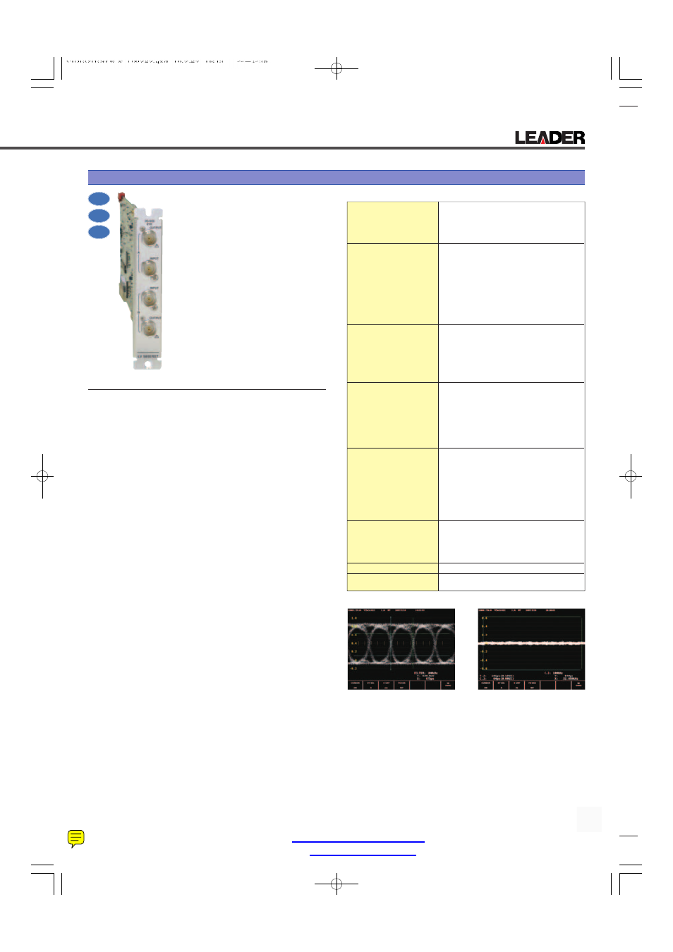
Plug-In Unit
Eye Pattern
Jitter
3G
SD-SDI
HD-SDI
The LV 58SER07 is a display unit. When it
is inserted into one of the input slots of the
LV 5800 or LV 7800 along with the LV
58SER06 (3G-SDI INPUT), it enables the
display and measurement of the eye pat-
terns and jitter of serial digital signals.
The LV 58SER07 enables the measure-
ment and observation of the physical char-
acteristics of not only 3G-SDI signals but
also HD-SDI and SD-SDI signals.
FEATURES
• Support for Three Types of SDI Signals
When the LV 58SER07 is used with the LV 58SER06 (3G-SDI
INPUT), it enables the display of eye patterns, the display of jit-
ter, and the execution of automatic measurements not only for
3G-SDI signals (both levels A and B) but also for HD-SDI and
SD-SDI signals.
• Two Switchable SDI Inputs
The LV 58SER07 has two input connectors that each support
three different SDI signal types. The controls on the LV 5800 or LV
7800 panel can be used to switch between the two inputs. (*1)
• Eye Pattern Display
Measurements of 3G-SDI signals have low noise and wide
bandwidth characteristics thanks to the use of a new kind of
circuit.
• Jitter Display
Because a phase detection method is used, accurate jitter
measurements can be performed even on degraded signals
for which eye patterns would not be useful. Also, V rate and H
rate sweep displays synchronized to the video signal are useful
for analyzing jitter that originates in digital video data.
• Simultaneous Eye Pattern and Jitter Display
When a serial digital signal is selected in the multi screen dis-
play of the LV 5800 or LV 7800, its eye pattern and jitter wave-
form can be displayed simultaneously. (*2)
• Filter Settings
The measurement of the timing jitter and alignment jitter of an
SDI signal can be performed through the switching of filters in
the eye pattern and jitter displays.
• Automatic Measurement
The automatic measurement feature enables the automatic
measurement of the amplitude, rise and fall times, and jitter
level of serial digital signals. The level of timing jitter and align-
ment jitter can be measured.
• Alarm Monitoring
The LV 58SER07 can display alarms and make log entries
when the values that it monitors exceed their user-specified
threshold values. The LV 58SER07 can monitor the rise time
(Tr), the fall time (Tf), the difference between the rise and fall
time (Tr-Tf), the timing jitter, and the alignment jitter of a serial
digital signal. (*3)
*1 When the LV 58SER07 is inserted in a device, only one LV 58SER06 (3G-SDI INPUT)
can be inserted in the device with it. Also, multiple LV 58SER07s cannot be inserted
into the same device or inserted into a device with the LV 58SER02. The LV58SER07
cannot be used with the LV 58SER01A.
*2 Simultaneous eye pattern and jitter display can only be performed for a single signal.
The simultaneous display of different signals is not possible.
*3 Alarm display and log recording are only valid in the eye pattern and jitter displays of the
LV 58SER07. Alarm monitoring cannot be performed in the background.
LV 58SER07 SPECIFICATIONS
Supported Formats
Data Rates
3G-SDI
SMPTE 424M 2.970 Gbps or 2.970/1.001 Gbps
HD-SDI
SMPTE 292M 1.485 Gbps or 1.485/1.001 Gbps
SD-SDI
SMPTE 259M 270 Mbps
Input Connectors
Eye-Pattern and Jitter
Display Input Connectors
Function
Input of SDI signals for eye pattern and jitter dis-
play
Input Connectors
2 switchable BNC connectors with A and B chan-
nels
Input Impedance
75 Ω
Connection Method
Connect to the rear panel of the LV 5800 or LV
7800 using a BNC cable.
Output Connectors
Dedicated Connectors for
Output to the LV 58SER06
Function
Dedicated output connectors for connecting to the
LV 58SER06 INPUT connector
Output Connectors
2 BNC connectors
Output Impedance
75 Ω
Eye Pattern
Display
Displays the input waveform before equalizing
Method
Equivalent time sampling
Jitter Filters
10 Hz, 100 Hz, 1 kHz, 100 kHz, TIMING, and
ALIGNMENT
Cursor Measurement
Amplitude measurement using Y cursors, time
measurement using X cursors, and rise time and
fall time measurement using the Tr and Tf cursors
Jitter Detection
Display
Displays the jitter component of an SDI input sig-
nal
Method
Phase detection method
Gain
x8, x2, or x1
Jitter Filters
10 Hz, 100 Hz, 1 kHz, 100 kHz, TIMING, and
ALIGNMENT
Cursor Measurement
Jitter value measurement through the use of cur-
sors
Automatic Measurement
Timing jitter and current jitter (the number of sec-
onds is indicated by sec, and the unit interval is
indicated by UIp-p) through the use of a phase
detection method, amplitude, and rise and fall
times of eye pattern waveforms
Environmental Conditions
Same as the LV 5800/7800
Accessories
Instruction manual...........................................1
Coaxial cable....................................................2
Leader Instruments Corporation web :
http://www.LeaderUSA.com
Tel. : 1 (714) 527‐9300
6484 Commerce Drive, Cypress, CA 90630
e‐mail :
Fax : 1 (714) 527‐7490
Document Outline
- Binder1.pdf
- LV58SER07 Data Sheet.pdf
- LV7800 WITH OPTIONS AND LV5800.pdf
- LV7800 WITH OPTIONS AND LV5800.pdf