Install receiver and test, Safety test, Install transmitter and test – Controlled Products Systems Group MWRT12 User Manual
Page 2: Cont
P.O. Box 159 • West Grove, PA 19390 • 800-220-3343 • 610-869-4422 • Fax: 610-869-4423 • www.milleredge.com
6809 South Harl Ave., Suite A • Tempe, AZ 85283 • 800-887-3343 • 480-755-3565 • Fax: 480-755-3558
3-
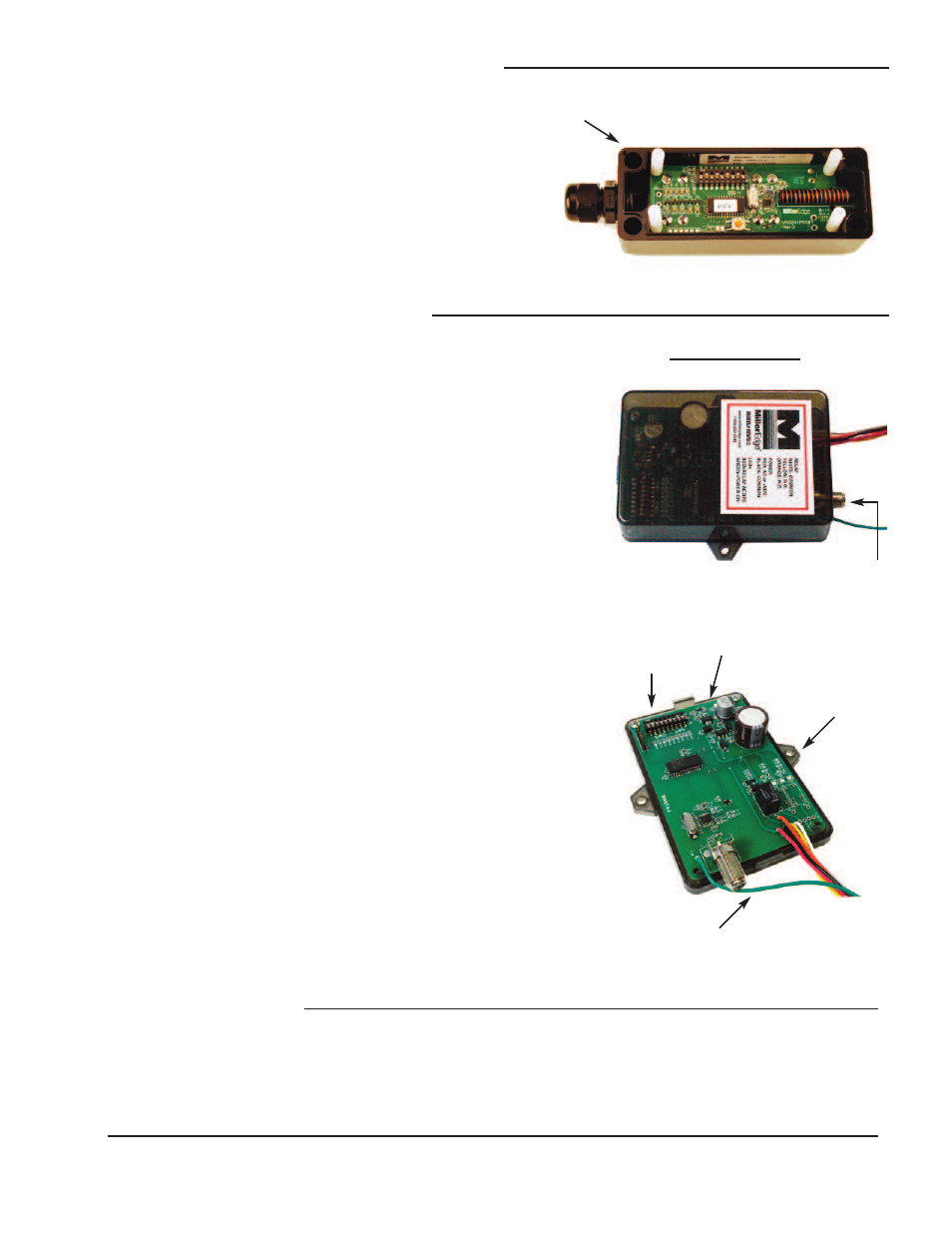
Install Receiver and Test
3-1. Set the
9 Pole, 3 Position Coding Switch on the Receiver to
match the Transmitter’s
9 Pole, 3 Position Coding Switch. Any
switch position will work as long as the Transmitter
coding switch
and the Receiver
coding switch are exactly matched (must be
different from other nearby transmitters of the same type).
3-2. Mount Receiver inside the operator control box so that the wires
from the receiver will reach the terminal strip on the operator.
3-3. Wiring:
a. The red (+) and black (-) wires are your power leads. They
connect to your operator panel terminals that provide the
appropriate power (12-24 VAC/VDC). Black wire is common,
Red wire is (+) or AC power.
b. The green wire is your standard antenna wire. This must be
located outside of any metal enclosure to provide for good
signal reception. There is an F-Connector antenna fitting
included on the receiver in the event a remote antenna
placement is needed.
c. Receiver Connections: The white wire will go to your
operator’s low voltage common terminal. If your operator
requires a normally open (N.O.) contact, connect the
yellow wire to the operator’s safety edge input. If the
operator requires a normally closed (N.C.) contact,
connect the orange wire to the operator’s safety edge input.
3-4.
Preliminary Test:
Confirm that once power is applied to the Receiver, it’s green
LED is lit. Now press the Transmitter's test button and notice
that the red LED lights up on the Receiver and the green LED
lights up on the Transmitter.
3-5. Replace the Receiver Top Lid.
4-
Safety Test
4-1. While closing the door or gate, momentarily activate the safety edge and confirm that
the motor stops and reverses the door or gate direction.
CH 1
ANTENNA
RECEIVER ENCLOSURE
(4) PRE-DRILLED
CORNER
MOUNTING HOLES
LED
INDICATORS
MOUNTING
SCREW
HOLES
2-
Install Transmitter and Test
Cont.
2-9. The four
(4) Pre-Drilled Corner Mounting Holes
are located on the far corners of the Transmitter
Enclosure. Mount the Transmitter to the gate
post, door end stile, or bottom angle using (4)
#6 - 20 x 3/4” self-drilling screws.
Mount the transmitter with the wire outlet facing
down or to the side.
2-10. Replace the cover on the Transmitter and
tighten the
Top Lid Screws, taking care to align
the lid.
MWTA12_Inst_20131007
9 POLE,
3 POSITION
CODING
SWITCH
F-CONNECTOR
ANTENNA
FITTING