Install receiver and test, Safety test – Controlled Products Systems Group MEL-K20 User Manual
Page 2
P.O. Box 159 • West Grove, PA 19390 • 800-220-3343 • 610-869-4422 • Fax: 610-869-4423 • www.milleredge.com
6809 South Harl Ave., Suite A • Tempe, AZ 85283 • 800-887-3343 • 480-755-3565 • Fax: 480-755-3558
2-9. Momentarily press the TEST button to load the address and group data. The Green Tx Data led should flash.
The Red Low Battery led will only light when the batteries fall below 2.4v.
2-10. Mount the Transmitter to the door using #6 - 20 x 3/4” self-drilling screws.The mounting holes are located under
the Top Lid. Mount the transmitter with the wire outlet facing down or to the side.
2-11. Replace the cover on the Transmitter and tighten the screws taking care to align the lid.
*Note the alignment pin located in the lower left corner.
3-
Install Receiver and Test
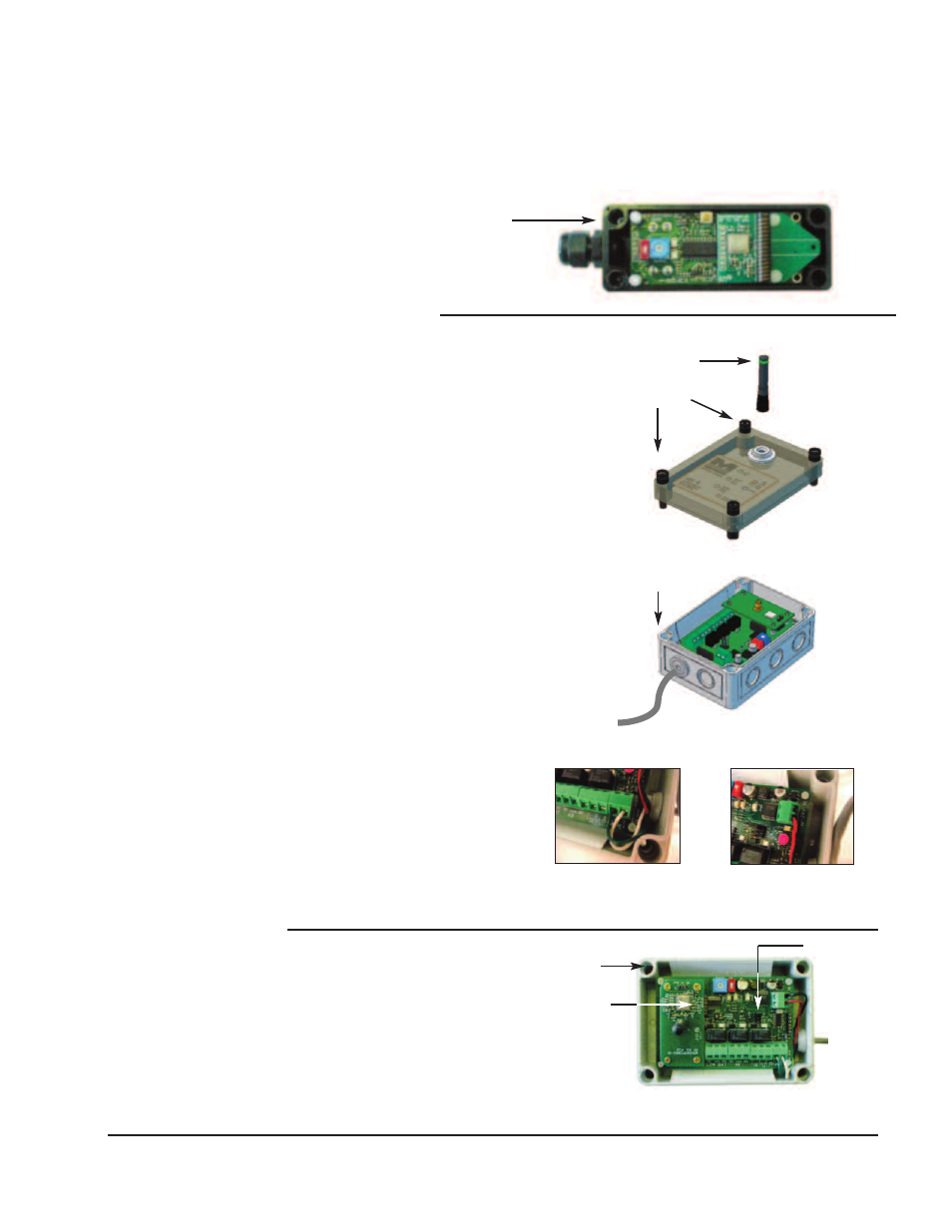
3-1. Loosen screws from the top lid of the Receiver Unit and
remove the lid.
3-2. Set the Group (red) and Address (blue) switches to
match the transmitter settings. (see Apendix)
3-3. Set the termination selection jumper to either 10k
resistive or 9.1v Diode (to suit the Operator).
3-4. Mount the receiver close to the operator and in the line
of sight of the transmitter using the pre-drilled mounting
holes as shown.
3-5. Connect the receiver’s PE (Photo Eye) output to the operator’s
photoeye input terminals using Green and White wires.
(operator terminal label naming may differ. Contact factory for
support). (See Pic.#1)
3-6. Connect 12/24V into 12/24VAC/DC source using Black and
Red wires. (See Pic. #2)
3-7. Connect the antenna to the receiver RF board.
3-8. Preliminary Test :
Confirm that the Transmitter and Receiver are powered ON.
Activate the Safety Edge (or monitored device).
The Address Valid Yellow led on the Receiver should
flashes momentarily.
IF the Address Valid led does not flash, check that the
Group and Address switches match the transmitter
settings. Confirm that the Photo-Eye and Safety Edge
leds are lit while the safety edge is held active.
Note that the Photo-eye and Safety Edge leds
go OFF when the Edge is released.
3-9. Replace the Receiver Lid taking
care to slip the Antenna
thru the top lid membrane.
4-
Safety Test
4-1. While moving the door in the downward
direction, momentarily activate the safety
edge and confirm that the door stops and
reverses direction.
INSIDE RECEIVER UNIT
TOP LID
SCREWS
ANTENNA
RECEIVER
ENCLOSURE
(4) PRE-DRILLED
CORNER
MOUNTING HOLES
TERMINATION
SELECTION
JUMPER
LED
INDICATORS
(4) PRE-DRILLED
CORNER
MOUNTING HOLES
RECEIVER
TOP LID
TOP LID MOUNTING
SCREW HOLES
3-5 Pic. #1
3-6 Pic. #2