Controlled Products Systems Group 414001 User Manual
Page 2
IF YOU ARE USING TWO MULTI-CODE 3021 OR 3028 TWO CHANNEL RECEIVERS:
Receiver Channel 1 - Set the receiver code switch Positions 1-8 to match transmitter side A
code switch positions 1-8. Set the 9th position on the receiver and transmitter side A to the
on (closed) position. Set the 10th position on the transmitter side A to the off (open) position.
Pushbutton 1 on your transmitter will now match Channel 1 on your #1 two channel
receiver (see fi gure 2 for side A and B transmitter code switch locations).
Receiver Channel 2 - Your receiver and transmitter side A code switch positions have
previously been set in the above step. Pushbutton 2 on your transmitter will match Channel
2 on your #1 receiver.
Receiver Channel 3 - Set the receiver code switch positions 1-8 to match transmitter side
B code switch positions 1-8. Set the 9th position on the receiver and transmitter side B
to the off (open) position. Set the 10th position on the transmitter side B to the off (open)
position. Pushbutton 3 on your transmitter will now match Channel 1 on your #2 two channel
receiver.
Receiver Channel 4 - Your receiver and transmitter side B code switch positions have
previously been set in the above step. Pushbutton 4 on your transmitter will match Channel
2 on your #2 channel receiver.
Once your codes have been set, check the operation and replace the lower cover.
TRANSMITTER INSTALLATION
The transmitter is completely self contained, including battery, and can be operated while
mounted in the car. It is supplied with a clip for attaching to the sun visor, if desired. If the
clip is used, attach to the case by sliding it into the recess provided on the back of the
transmitter until the small dimples fi t into the holes in the clip.
WARRANTY
ALL MULTI-CODE door related products carry a eighteen (18) month warranty against
defects in workmanship or material. This warranty begins at the date of manufacture, for
eighteen months. Linear LLC warranties our product only to our authorized dealers and
PRINTER’S INSTRUCTIONS:
INSTR,INSTL,MC4140,4CH,TX - LINEAR P/N: 215642 C - INK: BLACK - MATERIAL: 20 LB. MEAD BOND - SIZE: 9.000” X 3.500” - SCALE: 1-1 - SIDE 2 OF 2
TO SET YOUR TRANSMITTER AND RECEIVERS:
Receiver 1 - Set the receiver code switch positions 1-8 to match transmitter side A code
switch positions 1-8. Set the 9th position on the receiver and the transmitter to the on
(closed) position. Set the 10th position on the receiver and the transmitter to the off (open)
position (see fi gure 2 for side A and B transmitter code switch locations).
Receiver 2 - As you did in the procedure for Receiver 1, set your receiver code switch
positions 1 -9 to match transmitter side A code switch positions 1-9. Set 10th position on the
receiver to the on (closed) position (Note: The 10th position switch on the transmitter
side A has previously been set to the off (open) position In the above step).
Receiver 3 - Set the receiver code switch positions 1-8 to match transmitter side B code
switch positions 1-8. Set the 9 & 10th positions on the receiver and the transmitter side B to
the off (open) position.
Receiver 4 - As you did in the procedure for Receiver 3, set your receiver code switch
positions 1-9 to match transmitter side B code switch positions 1-9. Set the 10th position on
the receiver to the on (closed) position (Note: the 10th position switch on the transmitter
side B has previously been set to the off (open) position in the above step).
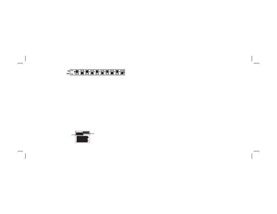
CODE SWITCH
SIDE A
CODE SWITCH
SIDE B
Figure 2
Figure 1
CODE SWITCH