Controlled Products Systems Group 307010 User Manual
Page 2
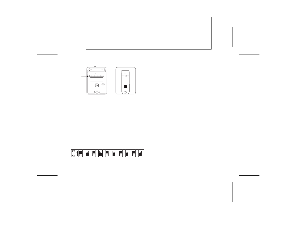
SELECTING A CODE
Set both transmitter and receiver switches to the code of
your choice, being sure both are set the same since a
different setting of just one switch will prevent opera-
tion. The digital code is determined by the position of 10
small switches numbered 1 through 10 located in the
receiver and transmitter. Any combination of “on” or
“off” positions can be selected by using a pencil or ball
point pen. (Note: The switches are in the “on” position
when the switch is depressed toward the number.) See
diagram # 2.
Once the codes have been set, check operation and
reassemble the transmitter case.
MICRO-TRANSMITTER INSTALLATION
This transmitter is completely self contained, including
battery and can be operated while held in hand or while
mounted in the car. It is supplied with “hook and loop”
fabric for easy mounting or it may be added to your key
chain using the slot provided.
TRANSMITTER BATTERY REPLACEMENT
Replacement battery - 12 volt alkaline lighter battery
(Eveready A 23 or equivalent)
The transmitter battery can be checked or changed by
opening the case using a small coin in the slot provided.
A twisting monion of the coin will separate the case
halves and provide access to the battery compartment.
Simply slide out the old battery and slide in the new,
remembering to observe the battery polarity molded on
the case in the bottom of the battery compartment.
Note that if the red L.E.D. on your transmitter fails to
light, you most likely have a weak or dead battery and it
should be replaced. (see diagram #1)
OPERATIONAL CHECK
To check operation, move back a reasonable distance
(about 50 ft.) and press the transmitter button. Operation
INSTR,INSTL,MC3070,MICRO-TX
LINEAR P/N: 214946 B
INK: BLACK
MATERIAL: 20 LB. MEAD BOND
SIZE: 6.250" x 4.500"
SCALE: 1-1
SIDE 2 OF 2
TRANSMITTER WITH TOP
HALF OF CASE REMOVED
TRANSMITTER TOP COVER
DIAGRAM #1
BATTERY
CODE
SWITCH
1
2
3
4
5
6
7
8
9
1
0
ON
OFF
CODE SWITCH
DIAGRAM #2