Controlled Products Systems Group EL24100 User Manual
Direct burial installation instructions, Basic loop layout guidelines to follow
BD
Loops
|
5362 Bolsa Ave. unit C | Huntington Beach, CA 92649
P: 714 890-1604 | F:714 890-1603 | C: 714 334-6978 | E: [email protected] | www.
BD
Loops
.com
Direct Burial Installation Instructions*
Preformed direct burial installation tips and directions
This is not a Saw-Cut Loop
for all saw-cut applications use
BD
Loops
preformed 3/16” saw-cut loop.
Installation in
Concrete
See Reverse side of this page.
(Pictures included)
Installation Under
Pavers
If the sub-base is concrete or
a slurry do not use this loop.
Saw-Cut in a loop instead.
Determine loop position and
footprint to include lead-in run to
gate operator. Be sure to use the
correct loop size.
*
Dig a 2” wide by 3-4” deep
trench in the pattern of the loop
and lead-in. (See Figure 1)
Fill Trench with one inch of sand.
Place loop in trench and run
lead-in through
½” schedule 40
or 80 rigid PVC. Glue all PVC
joints with a
a proper PVC
solvent cement
.
Cover loop and lead-in PVC run
with 2½” of sand.
Installation under
Asphalt
Position and shape the loop on
sub-base. Be sure to use the
correct loop size.
*
Pull lead-in through ½
” schedule
40 or 80 rigid PVC. Glue all PVC
joints with a
a proper PVC
solvent cement
.
Dig a
2” wide by 3-4” deep trench
in the size and place of the loop
footprint and lead-in.
Fill the trench with one inch of
sand base.
Lay the loop and lead-in run in the
trench on top of sand base and
use supplied ground stakes to
secure the loop corners.
Cover loop and lead-in PVC run
with 2½
” of sand.
Installation in
Gravel Road
Position and shape the loop on
sub-base. Be sure to use the
correct loop size.
*
Pull lead-in through ½
” schedule
40 or 80 rigid PVC. Glue all PVC
joints with a
a proper PVC
solvent cement
.
Dig a 7
” to 10” deep trench in the
size and place of the loop
footprint and lead-in.
Fill the trench with one inch of
sand base.
Lay the loop and lead-in run in the
trench on top of sand base and
use supplied ground stakes to
secure the loop corners.
Cover loop and lead-in PVC run
with 2½
” of sand. Compact sand
around the loop then fill in with
road base.
Harness Wire: Solder all connections
Plug/Screw Connectors: Tint all connections
Basic loop layout guidelines to follow
Reverse and Exit Loops
4ft from the gate/door.
Swing gates require 3ft from its
complete open and closed position.
2ft from each curb.
4ft from every other loop.
Shadow loops
Loop lies under the swing path.
3-4ft from the gates in its complete open
and closed position.
0-2ft from the curb. (Single Swing Gate)
Detection height is determined by approximately 2/3 of the short leg of the loop. Residential 4ft short leg (Detection of standard size
vehicles only).
Commercial 6ft short leg (Detect higher bed vehicles).
*Check BDLoops.com for the latest installation instructions
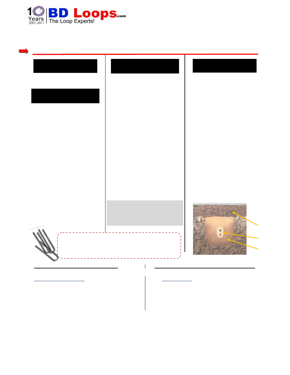
Loop should
be encased in
sand.
Soil
Loop
Sand
Figure 1
The ground stakes included with the loop are to help
hold the loop down while laying out a trench pattern.
When the loop is placed in the trench the ground stakes
are no longer necessary and should be discarded.
BD Loops
cannot
come in direct
contact with hot asphalt.
Call BD Loops for any questions
and to find a solution.