Ariens SNO-THRO 924333 - 1024 User Manual
Page 18
GB - 18
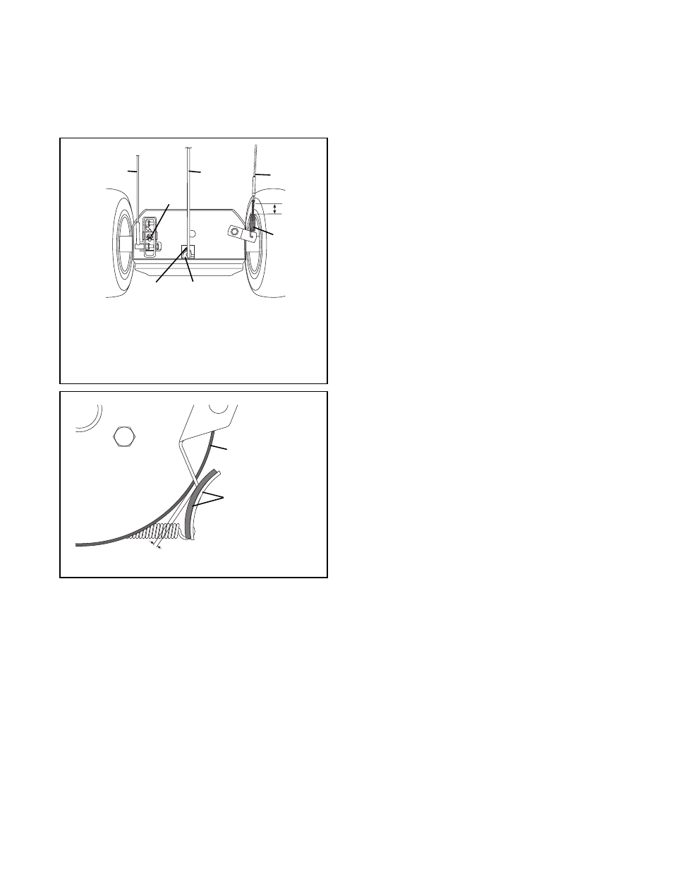
4. Measure distance between impeller brake shoe
pad and belt with attachment clutch engaged
(Figure 13). Impeller brake shoe should be 1/16"
(1,6 mm) minimum from belt. When attachment
clutch is disengaged, brake must contact belt. If
brake travel does not meet these requirements,
contact your Dealer.
TRACTION DRIVE CLUTCH
Adjust traction clutch to compensate for wear of friction
wheel when slippage occurs.
To adjust traction clutch:
1. Place speed selector in First (1) Forward.
2. Place unit in service position.
3. With traction clutch disengaged turn wheels while
tightening adjustment nut (Figure 12), at clutch
yoke, until wheels begin to drag.
4. Engage and release traction clutch.
5. Turn adjustment nut back three turns. Wheels will
then turn freely.
SPEED SELECTOR
1. Place unit into service position.
2. Remove cotter pin and washer (Figure 12) and
pull shift rod out of lever arm until it stops.
3. Put speed selector lever into fastest reverse
panel notch.
4. Adjust length of shift rod until rod end passes into
hole on selector lever arm.
5. Install rod into arm hole and secure with washer
and cotter pin.
DRIVE CHAIN
Chain should be taut with little or no play in it. To
compensate for looseness or excessive tightness in
drive chain.
1. Put unit into service position.
2. Remove bottom cover by removing four cap
screws.
3. Loosen nuts on idler hex shaft (Figure 17). Adjust
the idler hex shaft in slot as necessary. Torque
the nut to 70-146 in. lbs. (7,9 - 16,5 Nm).
ATTACHMENT DRIVE BELT
For Attachment Drive Belt Replacement:
1. Shut off engine and allow to cool completely.
2. Remove belt guard cover (Figure 15).
3. Remove spring clip from chute crank to remove
chute crank.
IMPORTANT: Disconnect remote cap deflector and/or
electric chute wire harness (if equipped) before
proceeding.
4. Loosen cap screws and carefully rotate belt
fingers out and away from belt and sheave
(Figure 14).
IMPORTANT: Use care when rotating the belt fingers.
DO NOT bend belt fingers out of shape.
5. Remove attachment drive belt from engine
sheave (it may be necessary to turn engine
sheave using recoil starter handle).
IMPORTANT: To avoid bending bottom cover, when
tipping unit apart, support handlebars firmly or tip unit
up on housing and remove bottom cover by removing
four cap screws before separating unit.
6. Remove cap screws securing housing to frame
(one on each side). Tip housing and frame apart
on pivot pins (Figure 15).
7. Remove auger drive belt from attachment sheave
(hold brake away from belt).
8. Place new attachment belt onto attachment
sheave.
9. Tip housing and frame back together and secure
with cap screws.
1. Attachment Clutch
Cable
2. Clutch Cable Spring
3. Traction Drive Clutch
Cable
4. Adjustment Nut
5. Speed Selector Shift
Rod
6. Cotter Pin and Washer
7. Lever Arm
3/8"
1
2
3
4
5
6
Figure 12
7
(9mm)
OS1181
1. Drive Belt
2. Brake Shoe
and Pad
1
2
Figure 13
1/16" (1.6mm)
OS0660