Cx-1200, Page 8 – CONTREX CX-1200 User Manual
Page 10
Page 8
CO_Sig
CO_Com
1
2
J3
TD/RD +
TD/RD -
Com
1
2
3
J1
+V_DO
DO_0
DO_1
DO_2
DO_3
DO_4
DO_5
DO_6
DO_7
Com
1
2
3
4
5
6
7
8
9
10
J2
L1
L2/NEUT
GND/PE
1
2
3
J4
* +12VDC
FI_1A
FI_1A
FI_1B
FI_1B
Com
FI_2A
FI_2A
FI_2B
FI_2B
Com
RI_1
RI_2
1
2
3
4
5
6
7
8
9
10
11
12
13
J5
DI_0
DI_1
Com
DI_2
DI_3
DI_4
DI_5
Com
DI_6
DI_7
1
2
3
4
5
6
7
8
9
10
J6
DI_8
DI_9
Com
DI_10
DI_11
DI_12
DI_13
Com
DI_14
DI_15
1
2
3
4
5
6
7
8
9
10
J7
-
-
-
-
+12V PWR
A
A
B
B
Common
A
A
B
B
Common
+12V PWR
-
-
-
-
Lead
Quadrature
Sensor
Feedback
Quadrature
Sensor
F-Stop
R-Stop
H-Stop
Run
Jog Fwd
Jog Rvs
Keypad Lockout
Spare
Block Select A
Batch Reset
Re-Learn
Open Loop
Position Reset
Sync Disable
Phase Advance
Phase Retard
RS485
Serial Comm
Digital Outputs
AC POWER
INPUT
Frequency Inputs
Reg In
Digital Inputs
Control
Output
To Drive
R
R
R
R
R
R
R
R
Zero Speed
Hi/Low Speed Alarm
Sync Alarm
Lead Sync Absent
Foll Sync Absent
Batch Done
Fwd/Rvs
Drive Enable
230 VAC
L1
L2
GND/PE
115 VAC
L1
NEUT
GND/PE
FUSES
1 A
250 V
RS485
Serial
Communications
Interface
EXTERNAL
DC
POWER
SUPPLY
(50V MAX)
+
-
Motor Drive
TD/RD +
TD/RD -
Com
Signal Input
Drive Common
CX-1200
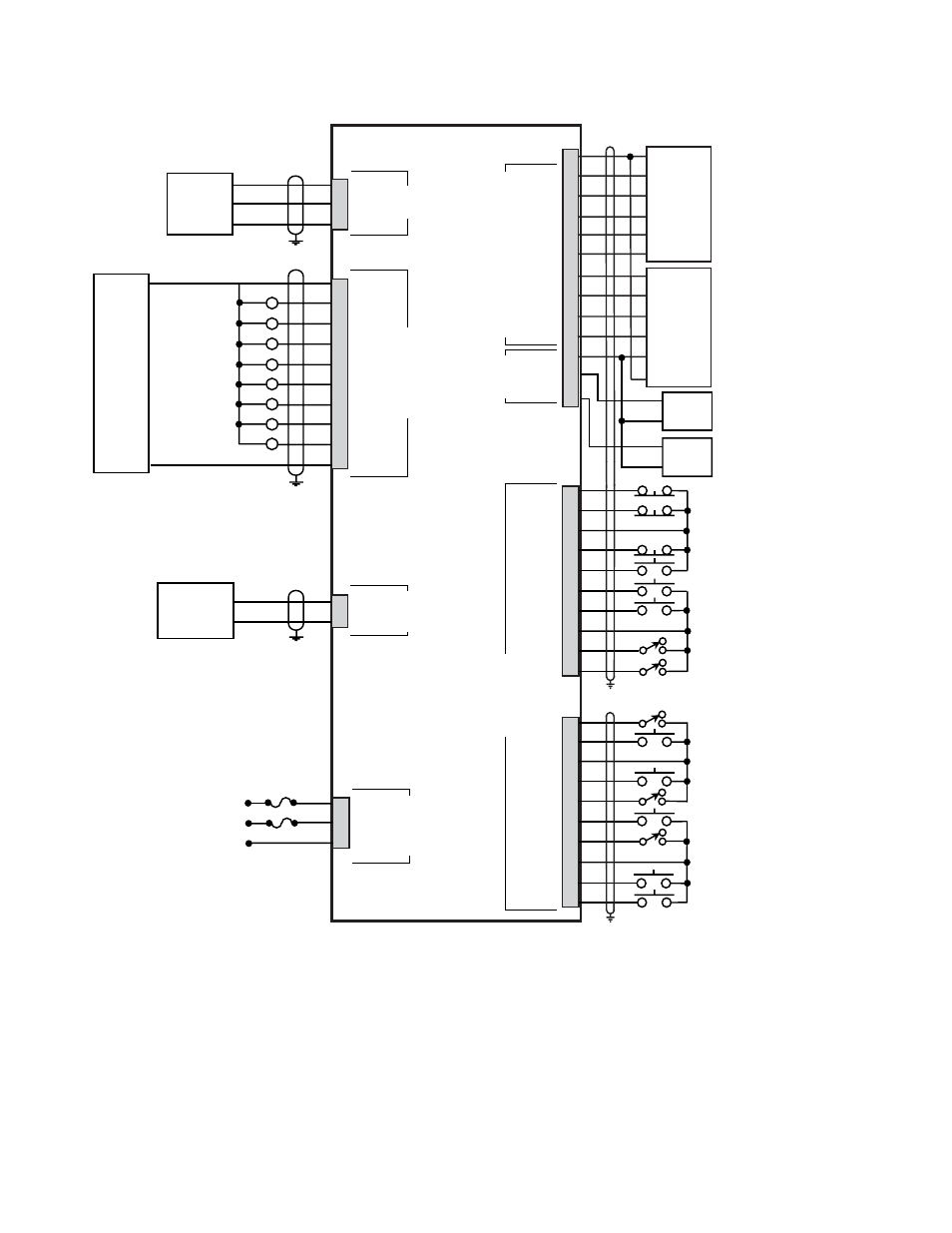
*
Power for frequency input sensors may be supplied by J5, pin 1.
Total current should not exceed 150 mA .
Foll Sync
Lead Sync
Figure 3 CX-1200 General Wiring