Chapter 4: motherboard information 4-16, P5bp-e/4l auxiliary panel connector aux_panel1 – Asus TS300-E5 User Manual
Page 92
Chapter 4: Motherboard information
4-16
®
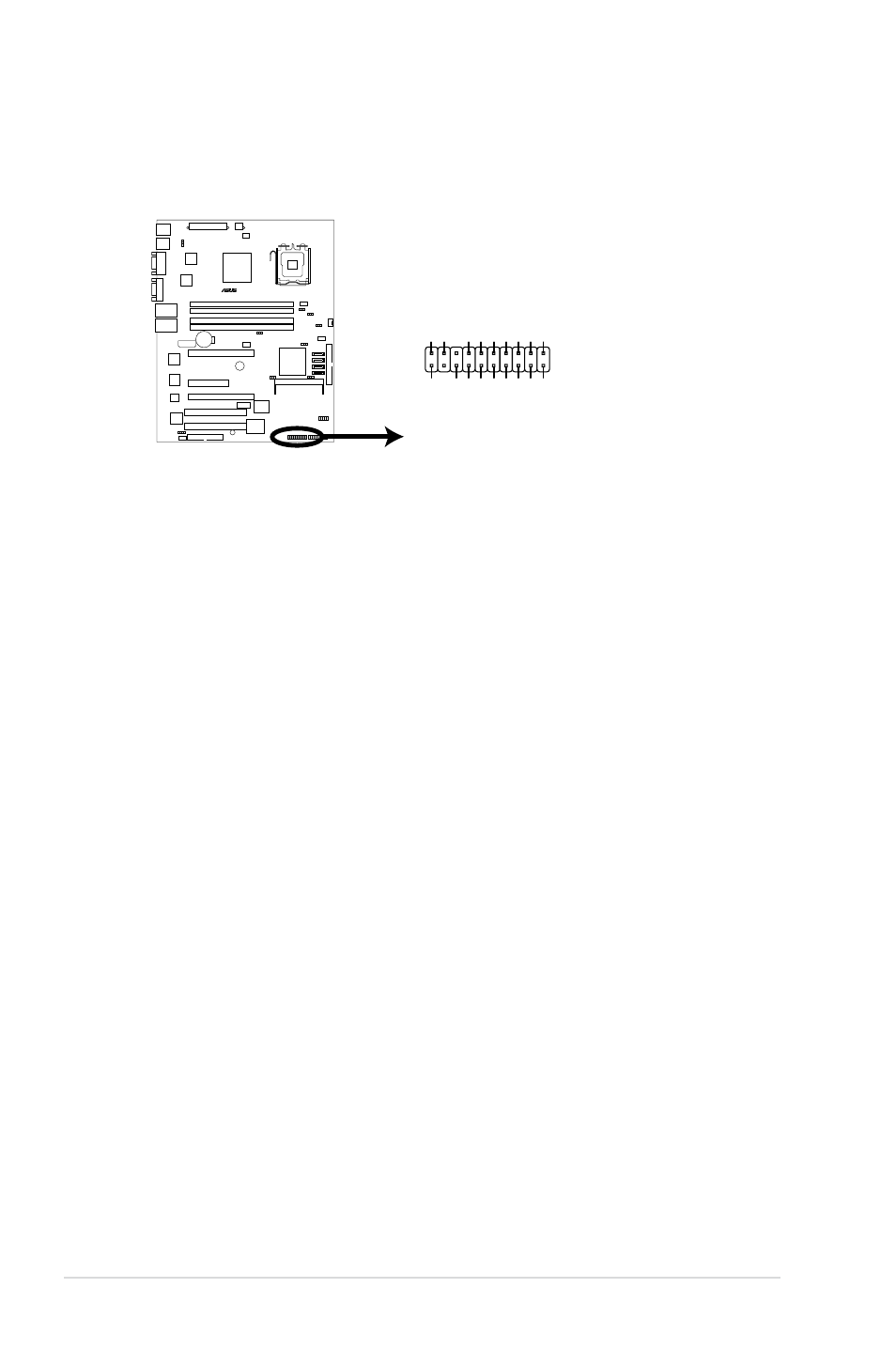
P5BP-E/4L Auxiliary Panel Connector
AUX_PANEL1
I2CD
AT
A_P
2
LOCA
TO
RLED1+
+5VSB
LOCA
TO
RLED1-
LAN1_LINKACTLED
+
LOCA
TO
RBTN
#
LAN1_LINKACTLED
-
GN
D
+5VSB
I2CCLK_P
2
GN
D
GN
D
LAN2_LINKACTLED
-
LOCA
TO
RLED2-
LAN2_LINKACTLED
+
LOCA
TO
RLED2+
CASEOPEN
1
NC
P5BP-E/4L
11. System panel auxiliary connector (20-pin AUX_PANEL1)
This connector supports several server system functions.
•
Chassis Intrusion connector (3-pin CASEOPEN)
This lead is for a chassis with an intrusion detection feature. This requires
an external detection mechanism such as a chassis intrusion sensor or
microswitch. When you remove any chassis component, the sensor triggers
and sends a high-level signal to this lead to record a chassis intrusion event.
•
LAN1 link activity LED (2-pin LAN1_LINKACTLED)
This 2-pin connector is for the LAN1 Activity LED. Connect the LAN1 Activity
LED cable to this connector. This LED blinks during a network activity and is
always lit when linked.
•
LAN2 link activity LED (2-pin LAN2_LINKACTLED)
This 2-pin connector is for the LAN2 Activity LED. Connect the LAN2 Activity
LED cable to this connector. This LED blinks during a network activity and
lights up when linked.
•
Locator LED 1 (2-pin LOCATORLED1)
This 2-pin connector is for the Locator LED 1. Connect the Locator LED
1 cable to this connector. This LED lights up when the Locator button is
pressed.
•
Locator LED 2 (2-pin LOCATORLED2)
This 2-pin connector is for the Locator LED 2. Connect the Locator LED 2
cable to this connector.
•
Locator Button/Switch (2-pin LOCATORBTN)
This connector is for the locator button. This button queries the state of the
system locator.
•
Front Panel SMBus (6-1 pin)
This connector allows you to connect SMBus (System Management Bus)
devices to the system front panel. Devices communicate with an SMBus host
and/or other SMBus devices using the SMBus interface.