5 connecting the csc-550 video to sxga / hd scaler, Connect – Comprehensive CSC-550 User Manual
Page 6
4
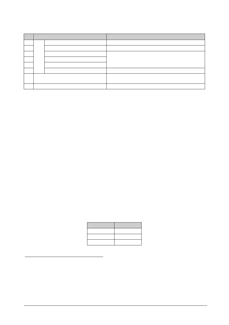
Table 2: CSC-550 Video to SXGA / HD Scaler Rear Panel Features
#
Feature
Function
12
YC 4p Connector
Connects to the s-Video source
13
CV RCA Connector
Connects to the composite video source
14
Y RCA Connector
15
C
B
RCA Connector
Connects to the interlaced
1
component video source
2
16
C
R
RCA Connector
17
IN
P
U
TS
SXGA PASS HD15 Connector
Connects to the VGA/Y, Pb, Pr source
3
18 SXGA / HD OUT HD15 Connector
Connects to the SXGA or HDTV (component video)
acceptor
19 12 VDC
+12V DC connector for powering the unit
5 Connecting the CSC-550 Video to SXGA / HD Scaler
Connect
4
your
CSC-550, as illustrated in the example in Figure 2:
1. Connect an s-Video source (for example, an s-Video camcorder) to the
YC INPUT 4p connector.
2. Connect a composite video source (for example, a composite video
player) to the CV INPUT RCA connector.
3. Connect a component video source (for example, a DVD player) to the Y,
Cb and Cr INPUT RCA connectors.
4. Connect an SXGA graphics source to the SXGA PASS INPUT HD15
connector
5
.
5. Connect the SXGA/HD OUT HD15 connector to a video acceptor (for
example, a plasma display) as follows:
When connecting to an XGA acceptor (RGBHV), then connect to
the acceptor’s XGA connector
When connecting to a component acceptor (Y, Cb, Cr), then
connect as shown in Table 3
Table 3: HD15 PINOUT for HD
6
PIN #
Signal
1
Cr
2
Y
3
Cb
1 Not compatible with progressive scan Y, Pb, Pr or HDTV
2 For component video, connect all three connectors: Y, Cb, Cr (also known as YUV)
3 This PC input signal is not scaled, but is available for pass-through when the PC source is selected
4 You do not have to connect all the inputs, connect only those that are required
5 This PC input signal is not scaled, but is available for pass-through when the PC Source is selected
6 The PINOUT should be: PIN 1 = Cr, PIN 2 = Y and PIN 3 = Cb (with pins 6, 7 and 8 as ground respectively)