Codelocks CL525 Mortice Lock with Double Cylinder User Manual
Page 6
STEP 1
Lightly mark a height line on
the edge and both faces of
the door, and the door jamb,
to indicate the top of the lock
when fitted. Mark a line down
the centre of the door edge,
extending above the height line
and 300mm below it.
STEP 2
Hold the template against the
edge of the door with the top
in line with the height line, and
with the arrows in line with the
‘Centre of Door Edge’ line.
Mark the positions of the
fixing screws, and the holes to
be drilled for the mortice.
STEP 3
Apply tape to the 16mm drill
bit at 90mm from the tip to
act as a depth guide when
drilling the mortice holes.
Ensure the drill is level and
parallel to the door face and
drill the holes as indicated
on the template. Remove the
remaining wood with a chisel
to leave a clean mortice hole
which accepts the lockcase
without forcing. With the lock
in the mortice make sure that
the forend is parallel with
the door edge and mark the
outline of the forend plate. Cut
the outline with a Stanley knife
to avoid splitting out when
chiselling. Chisel a rebate
sufficient to accept the forend
flush with the surface.
STEP 4
Fold the template accurately
along the dotted line and tape
it to the door face with the top
in line with the height line, and
the fold on the door edge. Mark
the centres of all the holes to
be drilled. Remove the template
and repeat the procedure on
the other face of the door.
STEP 5
Drill the holes from both
sides of the door to improve
accuracy and to avoid
splintering out the door face.
STEP 6
Install the lockcase in the
door.
STEP 7
Cut two of the black socket
head bolts to the required
length for your door.
Approximate overall length
should be door thickness plus
25mm to allow about 10mm
of threaded bolt to enter the
outside plate.
STEP 8
Take the BLUE or RED tipped
spindle and fit to the
code
side according to the hand of
your door (see diagram).
Fit the butterfly spindle to the
inside,
non-code side.
STEP 9
Check that the lever handles
are correctly fitted for the hand
of door. To change the hand of
a lever handle, loosen the grub
screw with the small Allen key,
reverse the lever handle and
fully tighten the grub screw.
STEP 10
Apply the front and back
plates, with the neoprene
seals in position, against the
door, over the protruding ends
of the spindle.
STEP 11
Fix the two plates together
using the socket head bolts,
starting with the top fixing.
Ensure that the two plates
are truly vertical and then
tighten the bolts using the ‘T’
shaped Allen key. Do not use
excessive force.
STEP 12
Before closing the door,
enter the code and check that
the latchbolt will retract when
the lever handle is depressed.
Now check the operation of
the inside lever handle. If there
is any binding of the handles
or the latch then loosen
the bolts and reposition the
plates slightly until the correct
position is found, and then
re-tighten the bolts.
STEP 13
Fit the double Euro-profile
cylinder and secure it with
the long screw through the
faceplate. Fit the cylinder
escutcheons.
STEP 14
Check that the deadbolt will
project and retract by key, and
that the key will also retract
the latchbolt.
Check that the inside lever
handle WILL retract the
deadbolt simultaneously with
the latchbolt.
Check that the outside lever
handle WILL NOT retract the
deadbolt.
STEP 15
Mark a vertical line on the door
jamb half the door thickness
away from the door stop. This
gives the centre line of the strike
plate. Align the Strike Plate
Template with the height line,
with the arrow heads aligned
with the centre line. Mark the
fixing holes, and draw around
the apertures for the latchbolt
and the deadbolt. Chisel out the
latch aperture to 12mm deep,
and the deadbolt aperture to
22mm deep.
Fix the strike plate with the top
screw only and gently close the
door. Ensure that the latchbolt
enters its aperture easily and
holds the door without too
much ‘play’. When satisfied,
draw around the final position
of the strike plate, remove it,
and cut a rebate to allow it to fit
flush to the surface. Re-fix the
strike with both screws.
Door hung on RIGHT
viewed from the code side
Door hung on LEFT
viewed from the code side
RED
BLUE
Door hung on RIGHT
viewed from the code side
Door hung on LEFT
viewed from the code side
Door hung on RIGHT
viewed from the code side
Door hung on LEFT
viewed from the code side
RED
BLUE
Door hung on RIGHT
viewed from the code side
Door hung on LEFT
viewed from the code side
BLUE
RED
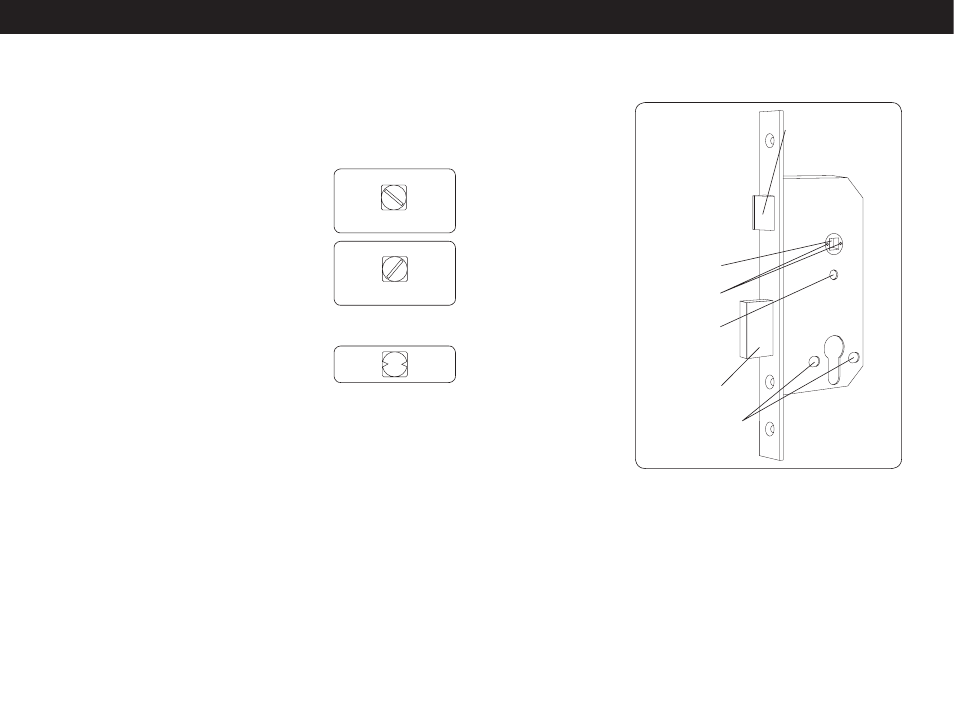
22mm bolt throw
Hole for bolt
through fixing
Grub screws
Split follower
Bolt through fixings
for escutcheons
Easy to reverse
key action latchbolt
FIGURE 2
520/525 lockcase
- CL520 Mortice Lock with Double Cylinder CL515 Tubular Mortice Latch Back to Back CL510 Tubular Mortice Latch Back to Back CL515 Heavy Duty Tubular Mortice Latch CL510 Heavy Duty Tubular Mortice Latch CL505 Panic Access Kit CL500 Panic Access Kit CL505 Front and Back Plates, Back to Back CL500 Front and Back Plates, Back to Back CL505 Front and Back Plates CL500 Front and Back Plates