Codelocks CL525 Mortice Lock with Double Cylinder User Manual
Page 4
STEP 1
Lightly mark a height line on
the edge and both faces of the
door, and on the door jamb,
to indicate the top of the lock
when fitted.
Crease the template along the
dotted line, and tape it to the
door with the top in line with
the height line.
Mark the 2x 12mm and the
1x 30mm holes. Mark the
centre of the door edge on the
Centre Line of Latch. Remove
the template and apply it to
the other side of the door,
aligning it accurately with the
first Centre Line of Latch mark.
Mark the 4 holes again.
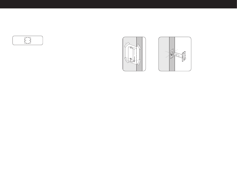
STEP 2
Keeping the drill level and
square to the door, drill a
25mm hole to accept the latch.
STEP 3
Keeping the drill level and
square to the door, drill the
12mm and 30mm holes from
both sides of the door to
increase accuracy and to avoid
splintering out the door face.
STEP 4
Put the latch into the hole
and, holding it square to the
door edge, draw around the
faceplate. Remove the latch
and score the outline with a
Stanley knife to avoid splitting
when chiselling. Chisel a rebate
to allow the latch to fit flush to
the surface.
The model 510/515 has a tubular, deadlocking, mortice latch and may be used
as a new installation on a door, or where an existing latch is to be replaced.
MODEL 510/515 INSTALLATION INSTRUCTIONS
STEP 2 (continued)
Fit the butterfly spindle to the
inside,
non-code side.
STEP 3
Check that the lever handles
are correctly fitted for the
hand of door. To change the
hand of a lever handle, loosen
the grub screw with the small
Allen key, reverse the lever
handle and fully tighten the
grub screw.
STEP 4
Take the adaptor kit, item 13
on the contents page. Cut
the two M5 countersunk head
bolts to length to suit the door
thickness; i.e. door thickness
plus a maximum of 10mm
(no more than 5mm should
enter the front plate). Hold
the front plate, with the three
hole neoprene seal, against
the door over the protruding
spindle. From the other side
of the door, fix the adaptor
plate to the front plate using
the two M5 countersunk
bolts. Before tightening up
the fixings, make sure that
the spindle hole is centrally
positioned over the follower.
Do not use excessive force.
STEP 5
Cut one of the long black
socket head screws to the
required length for your door.
Approximate overall length
should be door thickness
plus 25mm, to allow about
10mm of threaded bolt to
enter the front plate.
Place the neoprene gasket
over the adaptor plate.
Use the screw with the
‘T’ shaped Allen key, to fix
the back plate to the front
plate through the TOP hole.
Using the 20mm socket
head screw fix the back plate
through the BOTTOM hole
to the adaptor plate. Do not
use excessive force.
STEP 6
Before closing the door,
enter the code and check
that the latchbolt retracts
when the lever handle is
depressed. Now check the
operation of the inside lever
handle. If there is any binding
of the handles or latch then
loosen the top and bottom
bolts and reposition the
plates slightly until the correct
position is found, and then re-
tighten the bolts.
STEP 5
Fix the latch with the wood
screws, with the bevel towards
the door frame.
STEP 6
Fitting the strike plate.
NB: The plunger beside the
latchbolt deadlocks it, to
protect against manipulation
or ‘shimming’. The strike plate
must be accurately installed so
that the plunger CANNOT enter
the aperture when the door is
closed, even if it is slammed shut.
Position the strike plate on the
door frame so that it lines up
with the flat of the latchbolt,
and NOT the plunger. Mark the
positions of the fixing screws,
and draw around the aperture
of the strike plate. Chisel out
the aperture 15mm deep to
receive the latchbolt. Fix the
strike plate to the surface of
the frame using only the top
fixing screw. Gently close
the door and check that the
latchbolt enters the aperture
easily, and is held without too
much ‘play’. When satisfied,
draw around the outline of
the strike plate, remove it and
cut a rebate to enable the
faceplate to lie flush with the
surface. Re-fix the strike plate
using both screws.
NB Ensure enough room
for the latch support post
NB Space required above
latch body for cam to rotate
- CL520 Mortice Lock with Double Cylinder CL515 Tubular Mortice Latch Back to Back CL510 Tubular Mortice Latch Back to Back CL515 Heavy Duty Tubular Mortice Latch CL510 Heavy Duty Tubular Mortice Latch CL505 Panic Access Kit CL500 Panic Access Kit CL505 Front and Back Plates, Back to Back CL500 Front and Back Plates, Back to Back CL505 Front and Back Plates CL500 Front and Back Plates