CNB IXC2050IR User Manual
Page 8
XNET Network Weatherproof Camera Installation Guide
8/20
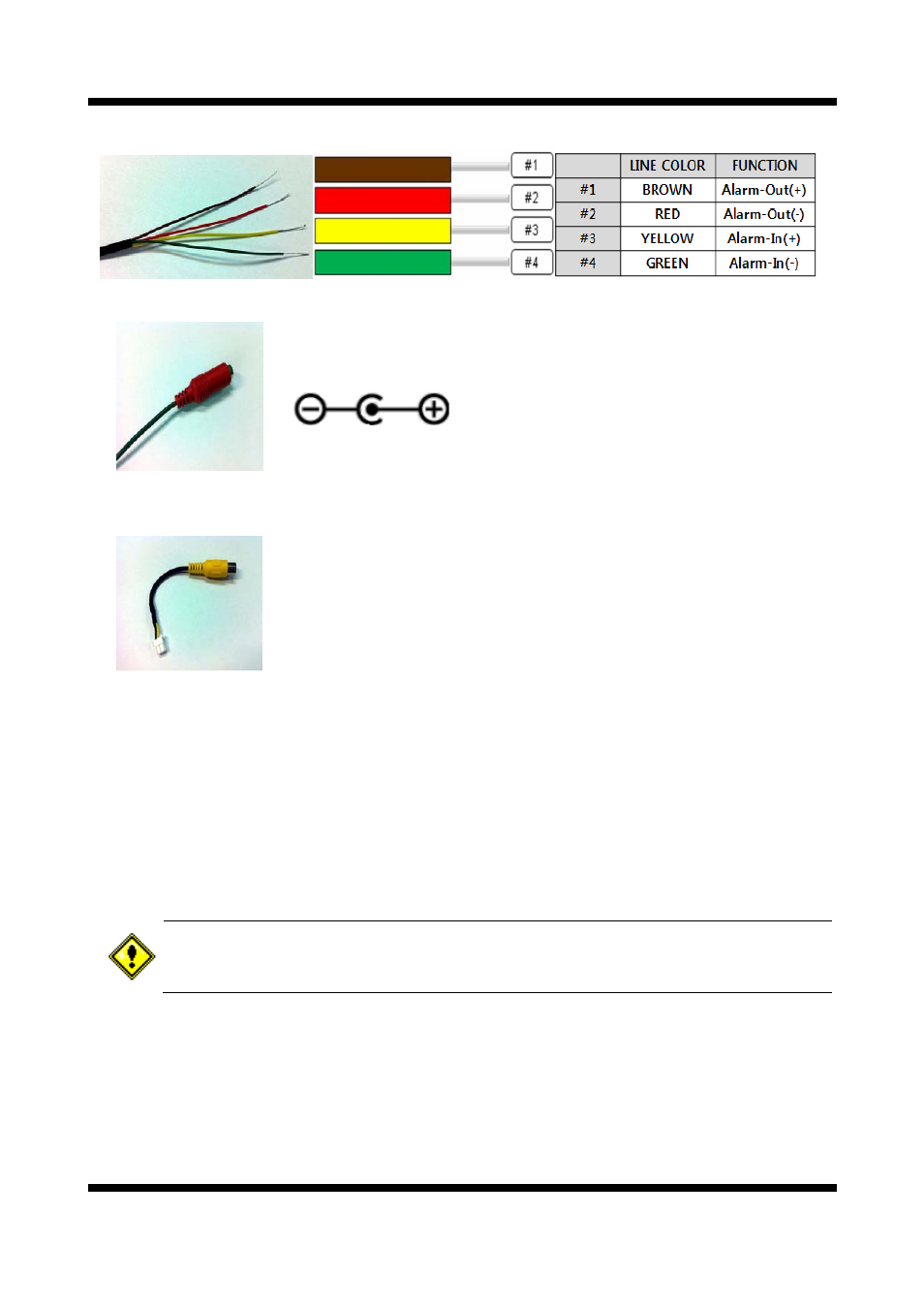
2.3.3 Cable Connection
Power Input
Use the cable adapter in the package to connect power.
Please use the accessory power supply provided in the package. (DC12V/2A)
Analog Video Output
Use this output for immediate monitoring of the video during installation.
Use the supplied cable adapter (Yellow for video and Black for Video Ground GND)
This adapter can be connected to a cable through a RCA termination.
(Select Video Out at menu screen to enable this output)
Alarm Connection
These wires connect to Alarm input/output devices.
Alarm Sensor Input: Connect to Alarm sensor devices such as IR Sensor or Heat sensor. These can
be configured to
normally close or normally open operation. (#3, #4)
Alarm Output: Connect to Alarm devices such as Relay operated
Siren Lamp or Alarm Light.
These can be configured to
normally close or normally open operation. (#1, #2)
Please refer to “2.3.4 Connection to Alarm Devices” for detailed instruction on how to connect
sensors and Relays.
Do not use this connector when powering up the product through LAN cable(PoE). The
product is not covered under warranty when it is damaged by connecting both Ethernet power
and 12V DC power to this terminal.
Network Cable
This Ethernet terminal connects to 100Mbps LAN through an RJ-45 cable. When optional PoE is used,
the power will be supplied from the Network Cable. Network cable of this product is not water proof