CNB IVP5035VR User Manual
Page 8
X
X
N
N
E
E
T
T
N
N
e
e
t
t
w
w
o
o
r
r
k
k
V
V
a
a
n
n
d
d
a
a
l
l
D
D
o
o
m
m
e
e
C
C
a
a
m
m
e
e
r
r
a
a
I
I
n
n
s
s
t
t
a
a
l
l
l
l
a
a
t
t
i
i
o
o
n
n
M
M
a
a
n
n
u
u
a
a
l
l
8 / 20
Alarm Connection
These wires connect to Alarm input/output devices.
Alarm Sensor Input: Connect to Alarm sensor devices such as IR Sensor or Heat sensor. These can
be configured to
normally close or normally open operation. (#1, #2)
Alarm Output: Connect to Alarm devices such as Relay operated
Siren Lamp or Alarm Light.
These can be configured to
normally close or normally open operation. (#3, #4)
Please refer to “2.3.3 Connection to Alarm Devices” for detailed instruction on how to connect
sensors and Relays.
Do not use this connector when powering up the product through LAN cable. (PoE)
The product is not covered under warranty when it is damaged by connecting both
Ethernet power and 12V DC power to this terminal.
Factory Reset
Press and hold for more than 3 seconds while power is on to recall factory default settings
Network Cable
This Ethernet terminal connects to 100Mbps LAN through an RJ-45 cable. When optional PoE is used, the
power will be supplied from the Network Cable. Network cable of this product is not water proof
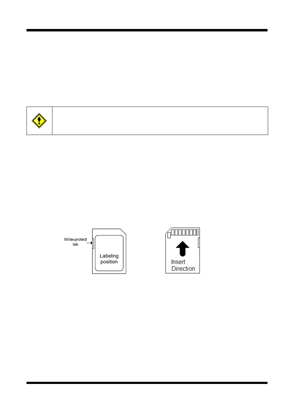
SD CARD SLOT : Enables recording of video data to an external memory device upon occurrence of
an event. Please use less than 16 GB SD Memory.
Figure 2-3. SD CARD