CNB IVP5035VR User Manual
Page 7
X
X
N
N
E
E
T
T
N
N
e
e
t
t
w
w
o
o
r
r
k
k
V
V
a
a
n
n
d
d
a
a
l
l
D
D
o
o
m
m
e
e
C
C
a
a
m
m
e
e
r
r
a
a
I
I
n
n
s
s
t
t
a
a
l
l
l
l
a
a
t
t
i
i
o
o
n
n
M
M
a
a
n
n
u
u
a
a
l
l
7 / 20
2
2
.
.
3
3
.
.
2
2
C
C
o
o
n
n
n
n
e
e
c
c
t
t
i
i
n
n
g
g
C
C
a
a
b
b
l
l
e
e
s
s
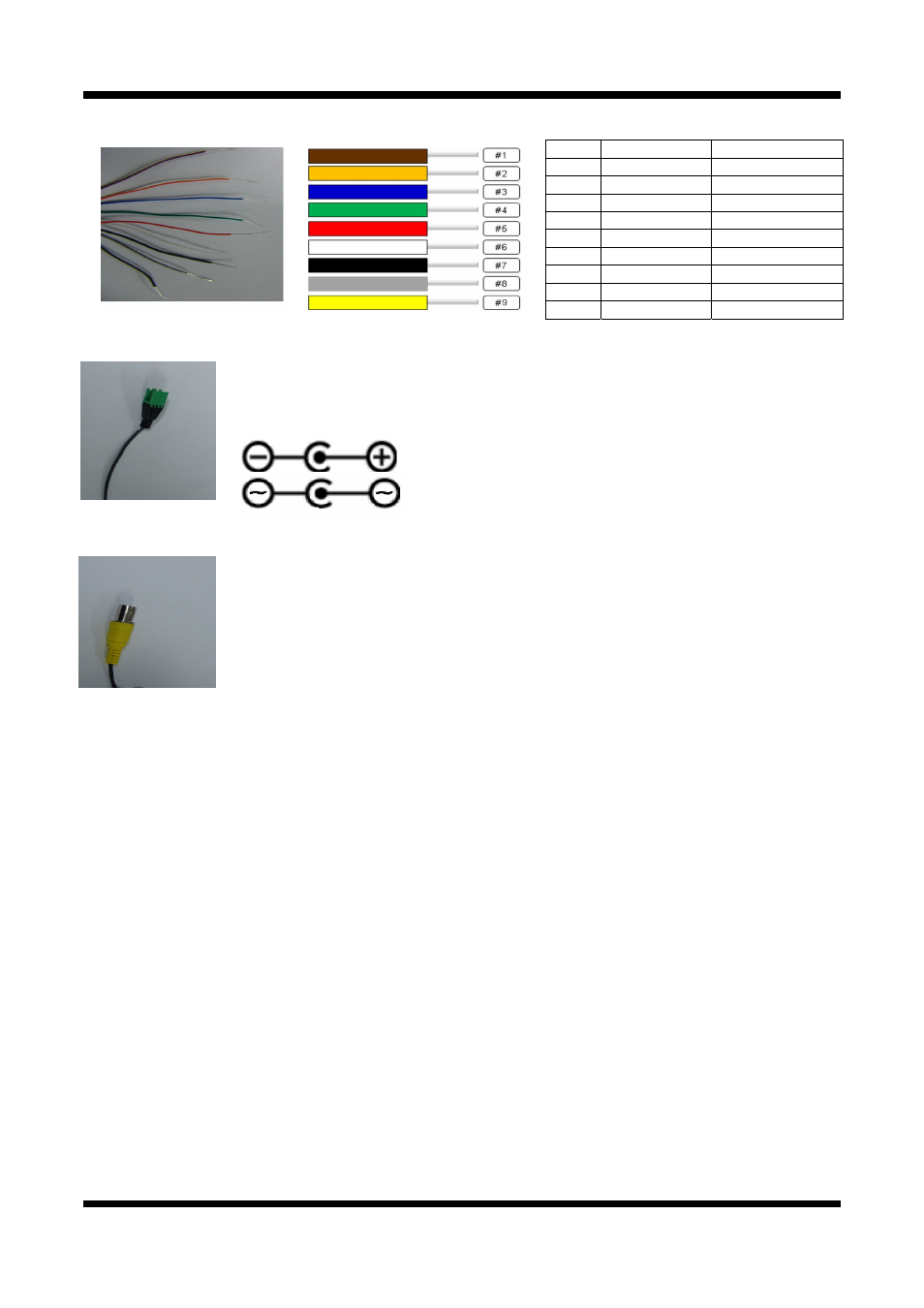
LINE COLOR
FUNCTION
1
BROWN Alarm-Out(+)
2
ORANGE Alarm-Out(-)
3
BLUE Alarm-In(+)
4
GREEN Alarm-In(-)
5
RED MIC/Line-in
6
WHITE Line-Out
7
BLACK GND
8
GRAY Not
Used
9
YELLOW Not
Used
Power Input(#1, #2)
Use the cable adapter(DC12V JACK) in the package to connect power.
Please use the accessory power supply provided in the package.
Except when connected to AC24V DC jack please use(DC12V/2A,AC24V 2.5A)
Analog Video Output
Use this output for immediate monitoring of the video during installation.
Use the supplied cable adapter
(Yellow for video and White for Video Ground GND)
This adapter can be connected to a cable through a BNC terminal Output connector.
(Select Video Out at menu screen to enable this output)
Audio Connection
MIC/Line Input (Mono)
Connects to auxiliary Audio device or microphone.
Line Output (Mono)
Audio signal output to a Power Amplified device or Speaker. This can be used to listen to the audio
signal sent from a remote PC for Bi-directional Audio communication.