CNB IVP5035VR User Manual
Page 6
X
X
N
N
E
E
T
T
N
N
e
e
t
t
w
w
o
o
r
r
k
k
V
V
a
a
n
n
d
d
a
a
l
l
D
D
o
o
m
m
e
e
C
C
a
a
m
m
e
e
r
r
a
a
I
I
n
n
s
s
t
t
a
a
l
l
l
l
a
a
t
t
i
i
o
o
n
n
M
M
a
a
n
n
u
u
a
a
l
l
6 / 20
2
2
.
.
3
3
.
.
H
H
a
a
r
r
d
d
w
w
a
a
r
r
e
e
D
D
e
e
s
s
i
i
g
g
n
n
a
a
t
t
i
i
o
o
n
n
2
2
.
.
3
3
.
.
1
1
.
.
S
S
w
w
i
i
t
t
c
c
h
h
a
a
n
n
d
d
C
C
o
o
n
n
t
t
r
r
o
o
l
l
s
s
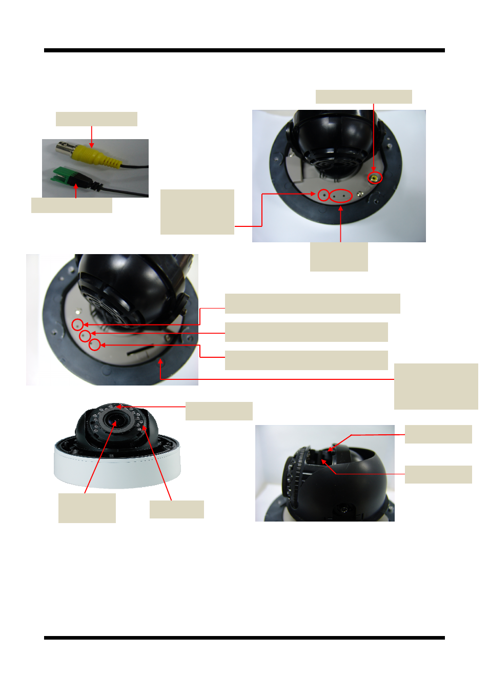
This shows Camera module inside the dome cover.
STATUS LED
PWR LED :
Red light indicates that 12V DC power is connected.
EVENT LED :
Green light indicates that Alarm Out signal is turned on.
SYSTEM LED : The system operates normally when the Green LED blinks
LINK LED : Red light indicates
that the network is properly connected.
ACT LED : Green light indicates that the XNET system connected to 100Mbps LAN. This green lamp
will blink If the system receives data.
Power Terminal
Factory Reset button
Recalls factory default
configurations
IR LED
Analog Video Output
CDS Sensor
Act,Link LED
Network status LED
Zoom Control
Focus Control
MEGA Fixel
VARIFOCAL Lenz
SD CARD
For Mounting the
Sd card SLOT
Analog video output
EVENT LED : EVENT
Alarm Out signal is turned
on.
SYSTEM LED : The camera at the end of boot
PWR LED :
that power is connected Indicates