3 digital voltmeter – Cleveland Motion Controls Classic Series DIN Rail Amplifier with Isolated Output MWI-13467 REV CA User Manual
Page 19
MAN-13467
R
EV
CA
C
LASSIC
S
ERIES
A
MPLIFIER W
/
I
SOLATED
O
UTPUTS
Page 19 of 30
While possible to interface the 4-20 mA current loop into circuits which do exhibit resistances between their burden
and the amplifier isolated COM, (refer to Figure 10.), this is a less desirable configuration. If you chose to wire the
amplifier in this way, you must keep the following in mind. When the commons of both circuits are connected, be
sure that the amplifier’s 4-20 mA OUT remains unconnected and that the 4-20 mA RET (J2-8) is connected to draw
loop current from a ground referred burden resistance at the receiving circuit. The burden resistance must not exceed
250 Ohms due to the reduced bias voltage, however a full-scale signal of -5.0 VDC is still possible (-5V= -20 mA x
250 Ohms).
8
+
5
7
6
3
4
2
1
1
4
2
3
6
5
7
8
4 to 20 mA
i
+
SHIELD GND
LOOP RESISTANCE
50 - 750 OHMS
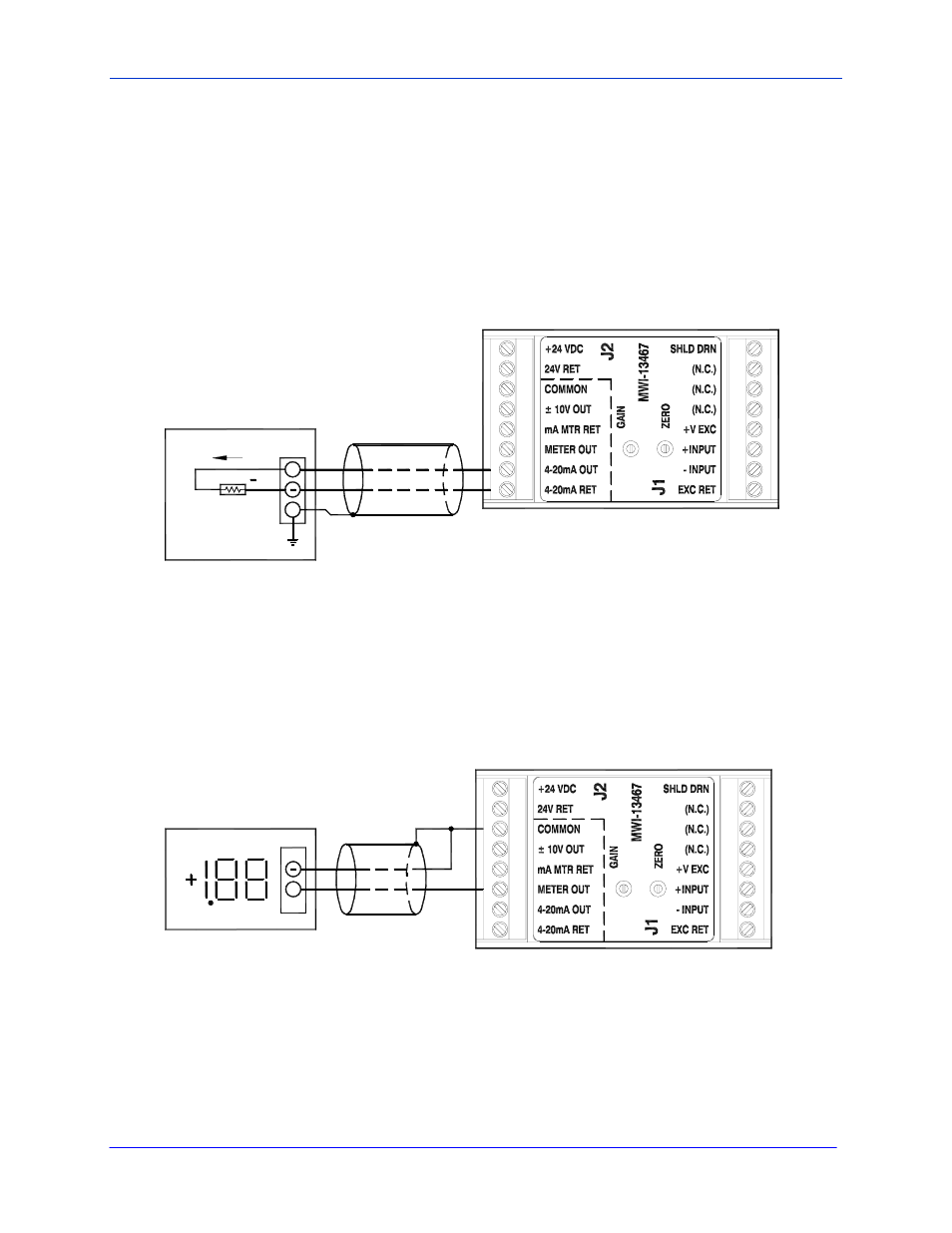
Figure 10 – 4-20 mA Output Wiring for Ground Referred Burden
2.12.2.3
DIGITAL VOLTMETER
The +/- output terminal is designed to provide +2.0 volts when the +/- 10 V output terminal is adjusted (with the
Gain and Zero pots) to be +10.0 volts (this is full scale). To achieve different scaling, adjust gains on the Digital
Panel meter (DPM).
MINIMUM METER RESISTANCE = 2000 OHMS
DIGITAL VOLT METER
0 TO 1.99 VOLT
+
8
6
5
7
3
2
4
1
3
2
4
1
8
7
6
5
Figure 11
Output Wiring, Damped +/- 2V Analog