Cleveland Motion Controls Classic CLT Cantilevered Transducer REV AA User Manual
Page 10
AO-70135
10 of 11
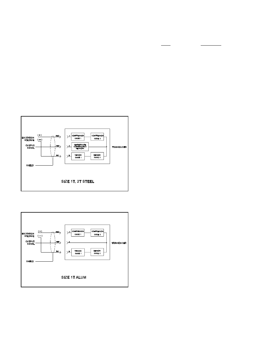
Figure 4
Figure 5
3.0 ELECTRICAL CONNECTIONS
Refer the the installation wiring diagram supplied with
the CLEVELAND-KIDDER tension indicator or
controller for making the transducer connections. Make
certain that the cable does not interfere with the web
path and that it is away from gearing or other moving
parts.
The following wiring diagrams are for reference only.
Most of the CLEVELAND-KIDDER indicators and
controllers will accept a half bridge input as shown in
Figure 4 or in Figure 5. See the applicable installation
wiring diagrams for the tension indicator or controller.
3.1
MATING CONNECTORS FOR
TRANSDUCERS
USE
CMC P/N
Mating Straight Connector,
Boot and Clamp Kit
MO-09854
Mating 90 Angle Connector,
"
Boot and Clamp Kit
MO-09855
3.2
INTRINSICALLY SAFE TRANSDUCERS
These transducers are intrinsically safe only when they
are part of a complete intrinsically safe system using the
TIX-1 tension indicator or wired per CMC control
drawings.
For transducers utilizing a 5.6 VDC (±2.8 VDC)
excitation voltage refer to CMC Control Drawing A800-
42273. For transducers utilizing a +5VDC excitation
voltage refer to CMC Control Drawing A800-42281.
Barrier block assemblies and/or the individual barrier
blocks may be purchased from CMC. Please contact
CMC for part numbers and pricing.
4.0 TEMPERATURE COMPENSATION
The size 1T and 2T steel transducers are supplied with
a temperature compensation network which is in series
with the output signal lead. The compensation circuit is
designed to be used with a tension amplifier which has
an input impedance of 5K Ohms. If other than the input
impedances given above are used, drift will occur in the
tension amplifier output when the transducer
temperature changes. Size 1T aluminum transducers use
a beam material that does not require temperature
compensation.
5.0 TROUBLESHOOTING
5.1
LOW OUTPUT SIGNAL
The transducer may have too large a maximum working
force for the application. Replace with a lower
maximum working force transducer or increase the web
wrap angle.