Selecting a mounting location, Determine a mounting style – Cleveland Motion Controls ULTRA SERIES SLIM CELL TRANSDUCER REV AA User Manual
Page 11
AO-70263
R
EV
AA
U
LTRA
S
ERIES
S
LIM
C
ELL
T
RANSDUCER
P
AGE
11
OF
18
2.2.4 S
ELECTING A
M
OUNTING
L
OCATION
Select the mounting location for the transducer keeping the following points in mind:
• The transducer can be mounted to either inside or outside of the machine frame.
• The tension-sensing roll must not be mounted where the web wrap angle can vary, or the
transducer will not interpret the tension properly. If a variance in the wrap angle occurs,
it is sensed by the transducer as a tension change and the change is indicated on the
tension indicator. In cases where it is impossible to mount the transducer where the wrap
angle does not vary, the change in indicated tension that results should be calculated and
if small, can be disregarded.
Figure 3 – Example of Varying Wrap Angles
WRAP VARIES
WRAP VARIES
PROCESS
OK FOR TENSION SENSING
2.2.5 D
ETERMINE A
M
OUNTING
S
TYLE
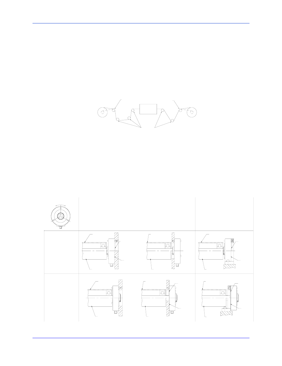
The Ultra Slim Cell Transducer can be mounted in several different ways (Figure 4). When choosing a mounting
style, evaluate your options by taking the following points into consideration:
• Safety
• Machine Frame orientation
• Ease of Assembly
Figure 4- Slim Cell Transducer Mounting Styles
62 DEG OF ANGULAR ALIGMENT
WITH BOLT IN POSITION
WITH DEAD SHAFT
BP
FLUSH
WITH LIVE SHAFT
BF
HF
WITH LIVE SHAFT
WITH DEAD SHAFT
WITH DEAD SHAFT
WITH LIVE SHAFT
BF
WITH DEAD SHAFT
FLUSH
WITH LIVE SHAFT
HP
HF
WITH DEAD SHAFT
FLUSH
BP
BF
WITH DEAD SHAFT
FLUSH
HP
HF
WITH MOUNTING
BRACKET
OUTSIDE
FRAME
INSIDE
FRAME
BLANK BACK
PLATE
BACK PLATE
WITH HOLE
WITH ALIGNMENT
PILOT
WITH LIVE SHAFT
WITH ALIGNMENT
PILOT
WITH ALIGNMENT
PILOT
WITH LIVE SHAFT
WITH ALIGNMENT
PILOT
Slim Cell may need to be mounted
to the roll and installed as a unit.