Hach-Lange BUHLER 1027 2000 User Manual
Page 51
Installation
Page 51
Manual BÜHLER 1027
Characteristic features: BÜHLER 1027 sampler
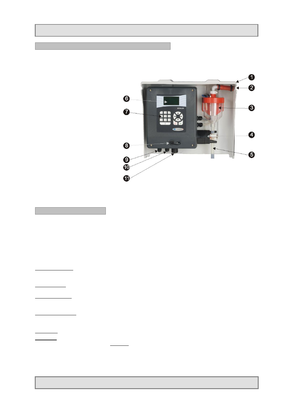
The device consists of the following component parts:
1. Housing/protective top
2. Suction hose connector
3. Metering vessel
4. Pinch Valve
5. Discharge tube
6. Control unit with back-lit
LC-display
7. Keypad
8. MiniUSB interface
9. Cable feedthrough for mains
cable
10. Cable feedthrough for air
inlet/outlet
11. Signal connector
Installing the apparatus
-
We recommend to install the apparatus as close to the sampling point as possible.
-
The hose has to be laid with a constant fall from the sampler to the sampling point as lower
lying points can lead to deposits in the hose which may freeze in winter or result in cross-
contaminations.
-
To fix the suction hose, we recommend to use the extraction unit available as accessory.
-
Immerse the end of the hose at the sampling point with the open end facing downstream
(direction of flow) so that coarse matter and fibres cannot be forced into the suction aperture
Mains connection
The device is equipped with a power supply lead.
The connecting data can be found in chapter “Specifications”.
Switch on / off
The device is switched on and off by means of the shock-proof plug.
Hose connection
The opening for connection of the suction hose is top right beside the dosing
unit.
Signal connections
The connector for signals (e.g. flow meter) is located at the bottom of the
control housing
Messages
Collective malfunction message (is directly connected to the relay).
Remark
:
The apparatus must be cleaned regularly in accordance with the degree of contamination present. In
view of the quality of samples, we recommend to clean thoroughly especially the wetted parts like dosing
unit, electrodes, distributor, bottles and inlet hose. Failure to do so could result in damage or destruction
to the equipment, device that
are not covered by warranty.