Autostart AS-1535 SH User Manual
Page 6
P.6 Installation
Guide
AS-1535 SH
NOTE: A Tach signal that is too low will cause the Module to “over
crank” and a Tach signal that is too high will cause the Module to
“under crank”.
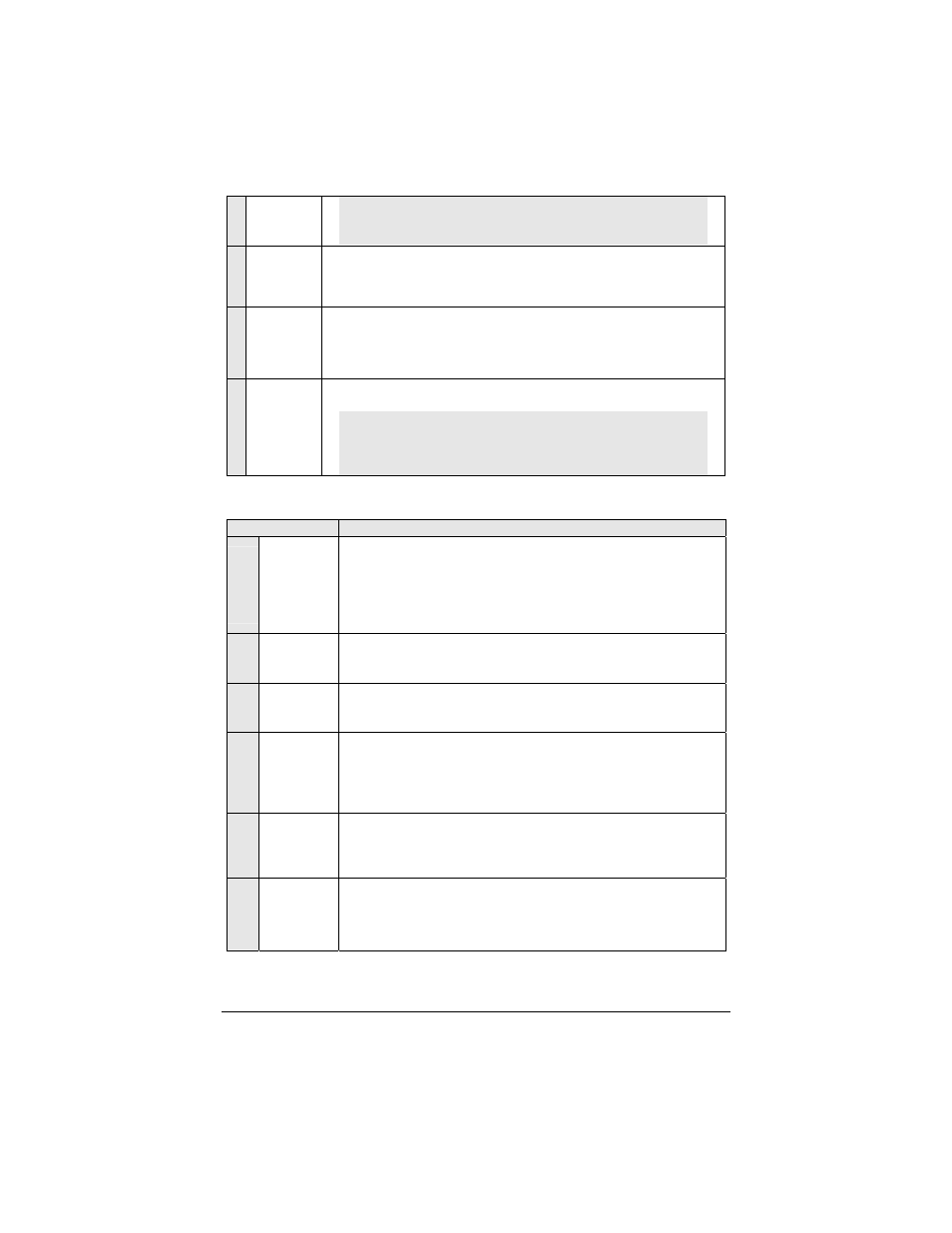
3
GREY
(-) Hood
Switch
input
Connect this wire to the Hood Pin-switch supplied. This input will disable or
shut down the Remote Starter when the Hood is opened. It is also used for
programming and therefore it is essential that it is installed.
4
ORANGE
(+) Brake
Switch
input
This wire must be connected to the Brake Light switch of the vehicle. The
wire should be +12 V only while the Brake Pedal is pressed. This input will
shut down the Remote Starter if the Brake Pedal is pressed. It is also used
for programming and therefore it is essential that it is installed.
5
YELLOW
+12 V
Parking
Light
output
This wire provides a +12 V output (15 A max.) and must be connected to
the Parking Light wire that tests +12 V when the Parking lights are
ON
.
Note: Ensure that the voltage does not vary when the dimmer control
switch is turned up or down. If this is the case, it is not the right wire.
There is a also a negative Parking Light output. Only one of these
two different outputs needs to be connected.
12-Pin Accessories Harness
Wire
Description
1
BLUE
(–) AUX 3
(Trunk)
output
500 mA negative output. This output can be used to control Trunk
release (1-sec. pulse) or can be set to operate as a constant output as
long as the
TRUNK
button is held pressed. (For Sunroof or Window
close).
Note:
AUX3
(
TRUNK
) operates only when Ignition is
OFF
or when the
vehicle is running under remote control.
2
BROWN
(–) Lock
output
Programmable 500 mA, 1/10-sec., 7/10-sec. or 4-sec. negative output.
3
GREEN
(–) Unlock
output
Programmable 500 mA, 1/10-sec., 7/10-sec., 4-sec. or a double ¼-sec.
pulse negative output.
4
WHITE /
BROWN
(–) Arm
output
500 mA ground output when the
LOCK
button is pressed. This output is
activated 500 ms before the
LOCK
pulse and deactivated 250 ms after
the
LOCK
pulse ends.
Note: The system will also give an
ARM/REARM
pulse on this wire when it
shuts down the vehicle after a remote start.
5
WHITE /
GREEN
(–) Disarm
output
500 mA ground output when the
UNLOCK
button is pressed. This wire is
for disarming OEM Alarm systems.
Note: System will also give a
DISARM
pulse before remote start.
6
BLUE /
WHITE
(-) Negative
AUX1
Output
500 mA ground output on the 2
nd
consecutive press of the
UNLOCK
button for Priority Door Access, or a Horn Confirmation on the first or
second press of the
LOCK
button –depending on the option that was
selected in the Programming Menu (see page 13).