Wiring overview, Wiring for power, Wiring overview wiring for power – Hach-Lange POLYMETRON 9500 User Manual User Manual
Page 14
Refer to the steps in this procedure to prevent ESD damage to the instrument:
• Touch an earth-grounded metal surface such as the chassis of an instrument, a metal conduit or
pipe to discharge static electricity from the body.
• Avoid excessive movement. Transport static-sensitive components in anti-static containers or
packages.
• Wear a wrist strap connected by a wire to earth ground.
• Work in a static-safe area with anti-static floor pads and work bench pads.
Wiring overview
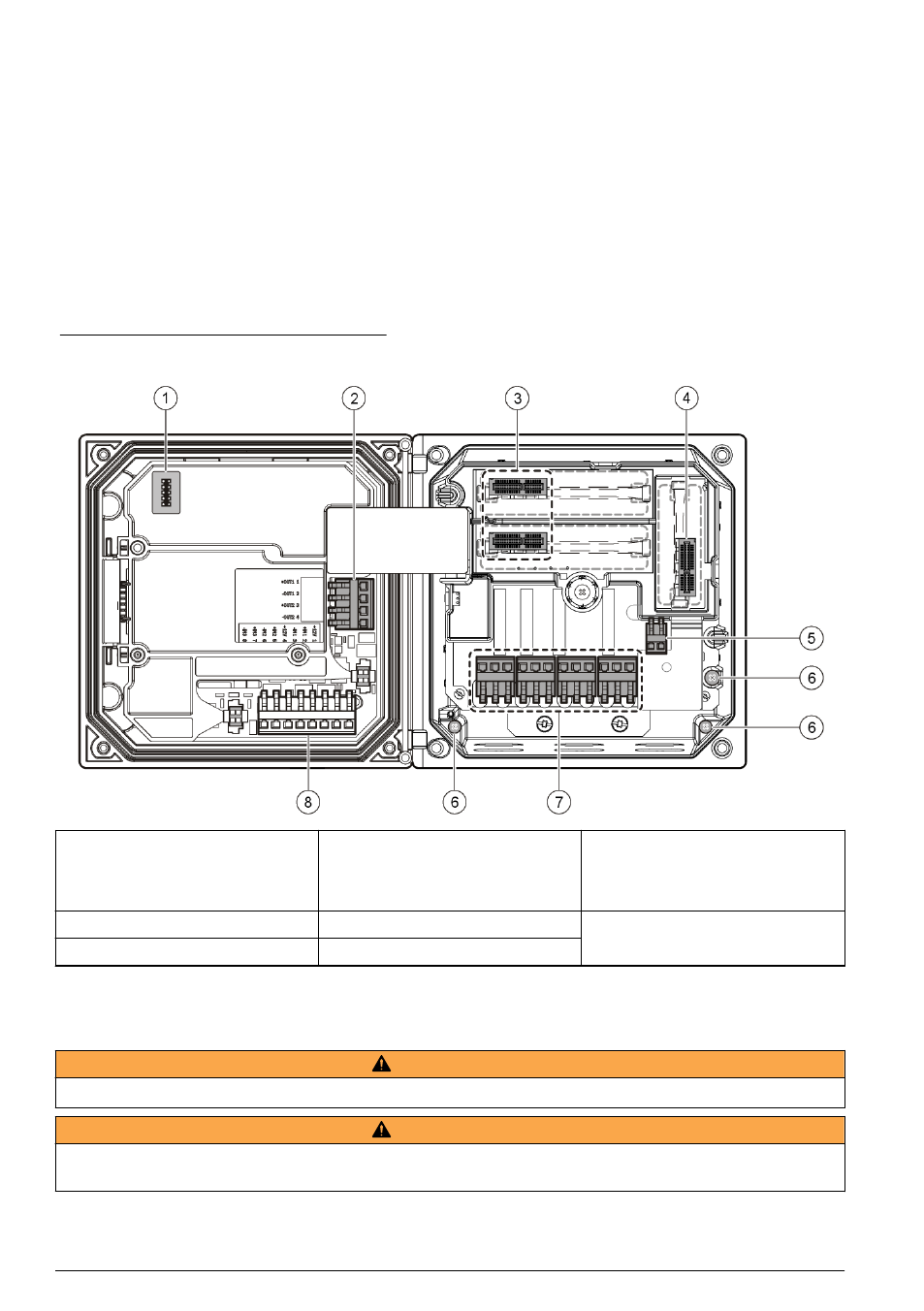
shows an overview of the wiring connections inside the controller with the high voltage
barrier removed. The left side of the figure shows the back side of the controller cover.
Note: Remove connector caps from the connectors before module installation.
Figure 7 Wiring connections overview
1 Service cable connection
4 Communication module
connector (e.g., Modbus,
Profibus, optional 4-20 mA
module, etc.)
7 Relay connections
1
2 4-20 mA output
1
5 AC and DC power connector
1
8 Discrete input wiring connector
1
3 Sensor module connector
6 Ground terminals
1
Terminals can be removed for improved access.
Wiring for power
W A R N I N G
Potential Electrocution Hazard. Always disconnect power to the instrument when making electrical connections.
W A R N I N G
Potential Electrocution Hazard. If this equipment is used outdoors or in potentially wet locations, a Ground Fault
Interrupt device must be used for connecting the equipment to its mains power source.
12 English