Warning – Cashco SCV-30 User Manual
Page 3
3
IOM-SCV-30
SECTION V
1. Maintenance procedures hereinafter are
based upon removal of the control valve unit
from the piping system where installed.
2. Owner should refer to their pro ce dures for re-
mov al, handling and cleaning of non-re us able
parts, i.e. gaskets, diaphragm, etc.
3. Valves supplied from the factory use a light
coat of Emhart Bostic White Food Grade
"NEVER_SEEZ" or equivalent on seals and
threads.
4. Reference Figures 2 through 5 for iden ti fi ca-
tion of item numbers.
5. All item numbers with respect to body as-
sem bly (BA) will be in parenthesis and not
un der scored; i.e. (1). All item numbers with
respect to the actuator assembly (AA) will be
in parenthesis and un der scored; i.e. (1).
B. Separation of Body/Actuator:
1. Place body assembly (BA) into a vise with
actuator as sem bly (AA) in upwards position.
2. Place matchmarks between the yoke (3),
bonnet (2), Tri-Clamp
®
(4), and body (1) to
assist in fi nal ori en ta tion when the body is
dis as sem bled and/or the actuator removed.
3. Using an overhead hoist, rig the actuator as-
sem bly (AA) for a vertical lift. Remove slack
from rigging.
4. Rotate yoke nut (8), CCW until fully dis-
engaged.
For ATO-FC Reverse Action Units:
Connect a temporary air supply hose that has an
ad just able airset with gauge to the ac tu a tor and
pres sur ize to a level suffi cient to initate travel to
upper limit of the bench range specifi ed on the
name plate (40). (Pressure will lift the plug/stem
V. MAINTENANCE
A. General:
(3.1) away from the body's (1) integral seat until
the plug is 100% open.).
For ATC-FO Direct Action Units:
Not necessary to connect temporary air supply.
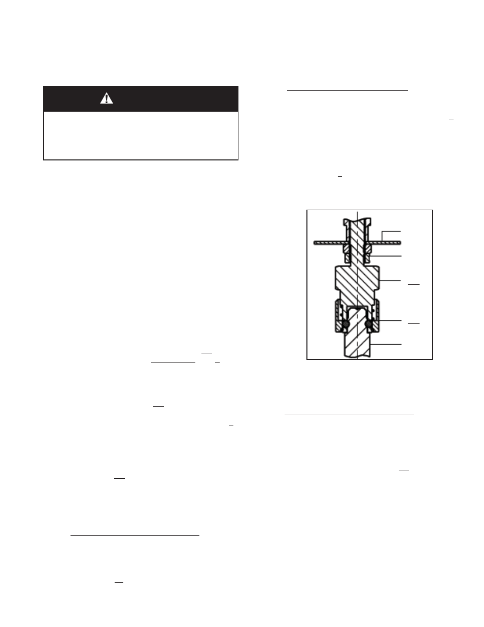
5. The valve plug/stem (3) -to-actuator stem (6)
assembly is a quick disconnect joint. Grasp
stem (3.1) between thumb and fore fi n ger of one
hand. Grasp the lower collar (42b) between
the thumb and fore fi n ger of the other hand.
Slide/push lower collar (42b) upwards. Stems
(3.1) and (6) should uncouple and separate.
NOTE: Take care to not “drop” the plug/stem (3.1)
down wards into the body’s (1) integral seat; lower
slow ly to this po si tion.
SYSTEM UNDER PRESSURE. Prior to per form ing any
body disassembly or removal for maintenance, in spec-
tion or cleaning, isolate the valve body from the system
and relieve all pressure. Failure to do so could result in
personal injury.
WARNING
6. Raise the actuator assembly (AA) over stem
(3.1).
For ATO-FC Reverse Action Units:
Release all pressure from the actuator. Lay actua-
tor assemby aside on work surface.
C. Body Disassembly:
1. Remove actuator assembly (AA) per Sec tion
V.B.1-6.
2. Grasp wing nut (4.2) with hand and rotate CCW
until there is suffi cient room to swing the nut
away from the restraining slot of clamp (4).
3. Hold plug/stem (3.1) securely, pull up wards,
lifting bonnet (2) and plug/diaphragm sub-
assembly away from body (1). It is nec es sary
to grasp the protruding "tab" on the di a phragm
(3.2) and pull upwards si mul ta neous ly with the
plug/diaphragm sub-as sem bly (3).
Figure 2:
Quick Disconnect
42a
42b
3.1
17
16