Cashco 964 User Manual
Page 2
IOM-964
2
Figure 1: Typical Control Valve Station
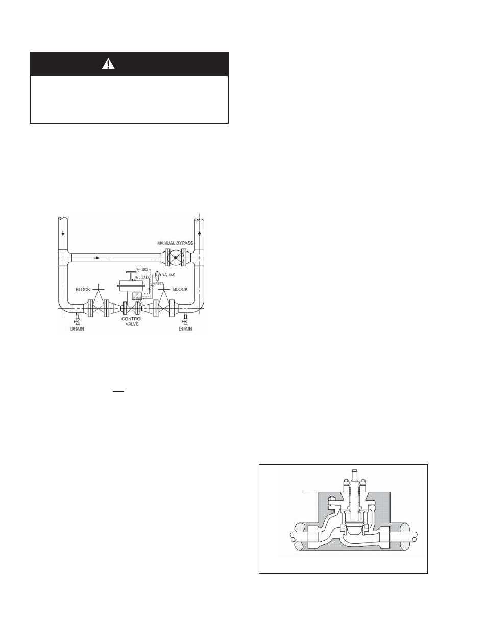
Figure 2: Body Insulation
SECTION III
2. Outdoors, all in stal la tions may be ori ent ed any
angle from hor i zon tal-to-vertical.
3. Valves are not recommended for in stal la tion
with the actuator oriented down wards.
.
B. Piping System:
1. It is recommended that the control valve unit
be in stalled with a double-block and bypass
as in di cat ed in Figure 1. This ar range ment is
rec om mend ed es pe cial ly where main te nance
will be done on the valve body while still in-
stalled in the pipeline.
2. Pipe unions are recommended for NPT
screwed or socket welded installations to al low
complete removal from sys tem. If re mov al
for main te nance is by cutting torch for socket
welded valves, leave suffi cient pipe nipple
space be tween the 964 body and the next
piping com po nent up or down stream to allow
socket weld couplings for re-in stal la tion.
3. If pipe reducers are located before and/or after
the valve body, keep the reducers as close as
prac ti cal to the valve body; this is especially
important where the reducers are more than
one line size larger than the valve body size,
which is common in gaseous ser vice.
4. Clean the piping of all foreign debris, in clud ing
chips, weld scale, weld spatter, oil, grease,
sand or dirt prior to in stall ing the control valve.
This is an absolute re quire ment for valves
supplied with composition soft seats. System
start-up strain ers, for removal shortly after
initial start-up, are rec om mend ed.
5. Field hydrostatic testing the com plet ed piping
system to 1-1/2 x CWP in psig indicated on the
nameplate, including the 964, is ac cept able.
If hydro test pressure exceeds the 1-1/2 x
CWP limit, the 964 must be re moved for such
testing. Before pres sur iza tion, the valve plug
should be lifted from the seat if of ATO-FC
action. Tighten packing as re quired.
6. In placing thread sealant on pipe ends prior
to en gage ment, ensure that excess ma te ri al
is removed and not allowed to enter the valve
upon start-up.
7. Flow Direction: Install so the fl ow direction
match es the arrow marked on the valve body.
8. For best performance, install in well drained
hor i zon tal pipe, properly trapped if a steam
service ap pli ca tion.
9. Valves are not to be direct buried un der ground.
10. Insulation may be applied as in di cat ed in Fig-
ure 2. Drain age away from the packing area
must be ensured when fully in stalled, sealed
and lagged for outdoors in stal la tion.
III. INSTALLATION
A. Orientation:
1. Recommended
ori
en ta tion when in stalled in
a hor i zon tal pipeline with the stem ver ti cal.
Valves may also be in stalled in ver ti cal pipe-
lines with stems hor i zon tal.
CAUTION
For welded installations, all internal trim parts and
seals, must be removed from body prior to welding
into pipeline. The heat of fusion welding will dam age
non-metallic parts if not re moved. NOTE: This does
not apply to units equipped with extended pipe nip ples.
Limit of
Bonnet
Insulation