CAME Flex U8711 Kit User Manual
Page 4
4
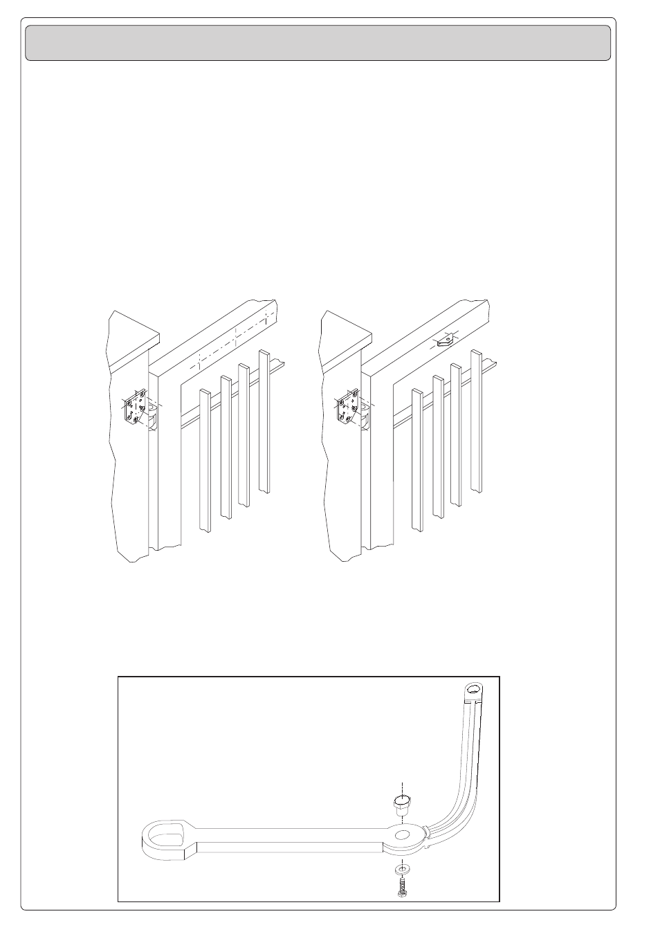
1) Tracciare gli assi e gli
ingombri dell’insieme
tenendo conto degli
schemi alle pag. 2 e
3, quindi fissare la
flangia di ancoraggio
del motoriduttore al
muro o al pilastro e, per
il motoriduttore F 500, il
supporto di ancoraggio
al cancello.
F500
F510
F500
1) Trace the centre lines
and external dimensions
of the entire assembly
in accordance with the
diagrams on pages 2
and 3.
Next, mount the flange
for the gear motor on the
wall or pillar, and mount
the anchor block for gear
motor F500 on the gate.
1) Tracer les axes et
les encombres de
l’ensemble en se
référant aux schémas de
page 2 et 3, puis fixer la
bride du motoréducteur
au mur ou au pilier. Pour
le motoréducteur F500,
fixer le support de
fixation au portail.
1) Die Achsen und
Außenabmessungen
der
Antriebseinheit
unter Berücksichtigung
der schematischen Dar-
stellungen auf Seite 2 und
3 aufreißen und dann den
Getriebe-motor-Flansch
an der Wand oder am
Pfosten befestigen und,
bei Verwedung des
Getrie-bemotor F500, die
entsprechende Befesti-
gungsvorrichtung am Tor
anbringen.
1) Trazar los ejes y
las dimensiones del
conjunto tenendo en
cuenta los esquemas
de pág. 2 y 3,poste-
riormente fijar la brida
del motorreductor a la
pared o al pilar y, para
el motorreductor F500,
el soporte de enclje a la
puerta.
2) Assemblare il braccio
snodato unendo i
due semibracci con
l’apposita bulloneria.
2) Use the hardware
provided with the unit to
join the two halves of the
articulated arm together.
2) Assembler le bras
articulé en reliant les
deux demibras avec la
boulonnerie prèvue à
cet effet.
2) Die beiden GelenKar-
mhälften mit den mit-
gelieferten Schrauben
zusammenfügen
2) Ensamblar el brazo
articulado uniendo
los semibrazos
con los pernos
correspondientes
ISTRUZIONI DI MONTAGGIO | ASSEMBLY INSTRUCTIONS | INSTRUCTIONS POUR LE MONTAGE
MONTAGEANLEITUNG
| INSTRUCCIONES DE MONTAJE