6 connecting to the control panel, English, Sx dx 5.7 manual release – CAME Frog-A 230v User Manual
Page 5: Fig. 5 fig. 5-a fig. 5-b
5
T
h
e d
at
a a
n
d i
n
fo
rm
at
io
n s
h
ow
n i
n
t
h
is
m
an
u
al
m
ay b
e c
h
an
g
ed by CAM
E
c
an
ce
ll
i a
u
to
m
at
ic
i s
.p
.a
. a
t a
n
y t
im
e w
it
h
o
u
t p
ri
o
r w
ar
n
ing
.
ENGLISH
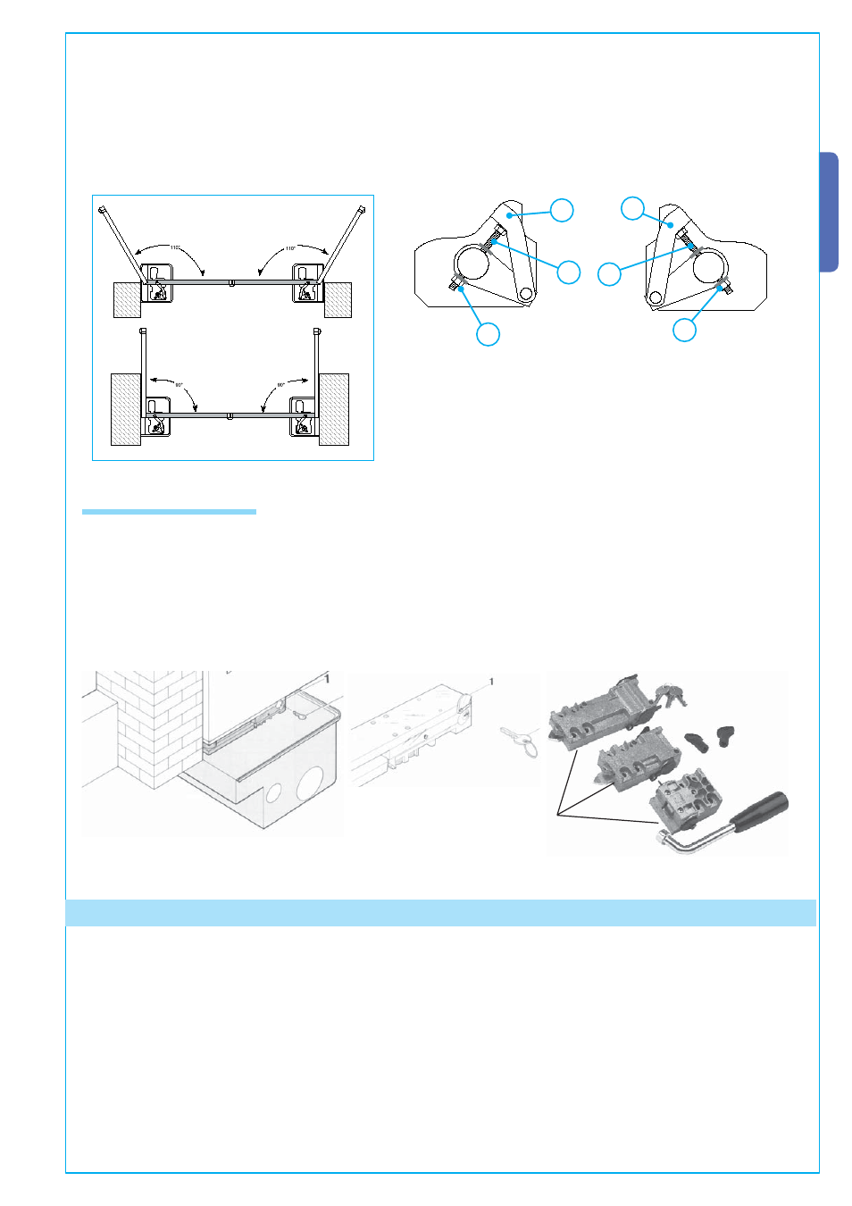
- Screw the M10 x 100 (A) and the M10 (B) bolt onto the gearmotor arm as shown in fi g. 4-1 (RIGHT HAND installation) and fi g.
4-2 N(LEFT HA D installation);
- Affi x the gearmotor to the foundation box using the threaded pins and securing it using the provided bolts and washers;
- insert the (C ) transmission lever between the motor arm and the box lever and electronically shut the gate against the closing
end stop. Adjust screw (A) until it touches the (C) transmission lever.
- When testing, adjust the screw so as to allow proper closing pressure of the gate leaf and allow its re-hooking during the mecha-
nism’s release procedure.
- Once adjustment is complete, secure the (B) nut.
Fig.4
DX
SX
Fig.4-1
Fig.4-2
A
B
C
C
B
A
SX
DX
5.7 Manual release
- In emergencies (i.e. power outages) the release mechanisms allow the gate to hook back up when closing.
- You may choose among three different release models: model A4366 with customised key (Fig. 5-A), model A4365 with tri-lobed
key and model A4364 with lever key (Fig. 5-B). We suggest greasing the release’s hook-up key (Fig. 5-B – part. 3); Consult the
documentation pertinent to the relative items for the release procedure.
N. B.: release operations are to be carried out during emergency procedures and with the power disconnected.
3
Fig. 5
Fig. 5-A
Fig. 5-B
A4366
A4364
A4365
6 Connecting to the control panel
- We suggest making the gearmotor cable connections in shunt boxes;
-
For further information concerning the functions, see the technical documentation for the (ZA3, ZA4, ZA5 or ZM2) control pa-
nels.