Hydrotech AP1 (115V) Air Pump & Retention Tank Kit User Manual
Page 5
4
SECTION 8: REGULATING AIR FLOW
To adjust the Air Regulator Valve, loosen lock nut (thin nut in middle of fitting). Now the outer adjustment nut can be turned
clockwise to increase pressure and air flow during well pump cycle. If threaded out too far, air will flow freely out of regulator
valve instead of pumping air into water line. Furthermore, if adjustment nut is removed, the check-ball and spring will fall
out. If this happens, simply insert ball and spring and thread nut back in.
While the well pump and Air Pump are running you can set the Air Regulator Valve (ARV) to desired pressure. Start with
ARV half way open. As you turn adjustment nut clockwise, pressure will build in pump head. When pressure at head
meets line pressure, air will be pushed into water line. To decrease or limit the introduction of air, set the ARV 5-10 pounds
above the start up pressure of well pump. When the well pump starts up, the air pump also turns on, adding air during the
beginning of pump cycle. Once the line pressure exceeds the setting on Air Pump ARV, no more air will be introduced into
water line. The Air Pump will continue to run during the rest of the pump cycle but the excess air will be released out of the
ARV (you should be able to hear or feel the air escaping). If more air is desired, gradually set ARV to a higher pressure.
After setting ARV adjustment nut, secure lock nut to regulator body by rotating clockwise. This will lock the setting of the ARV.
To re-adjust, loosen lock nut, reset adjustment nut and secure lock nut. Follow up visits may be required to fine tune ARV.
Well Pump Setting
ARV Setting
20 - 40 psi
30 psi
30 - 50 psi
40 psi
40 - 60 psi
50 psi
Pressure Switch Settings
Constant Pressure Setting
ARV Setting
40 psi
50 psi
50 psi
60 psi
60 psi
70 psi
Constant Pressure Settings
Variable Speed Pump Setting ARV Setting
40 psi
50 psi
50 psi
60 psi
60 psi
70 psi
Variable Speed Pump Settings
SECTION 6: INSTALLATION OF THE AIR PUMP WITH WELL PUMP PRESSURE SWITCH AS
THE POWER SOURCE
1.
Position close to electric source.
2.
Electrical connection: Install appropriate 115 volt or 230 volt receptacle and connect wire from receptacle to pump
(load) side of pressure switch. This will allow the Air Pump to turn on with the well pump.
3.
Plug Air Pump into receptacle. Run well pump through a few cycles. Fine tune or adjust Air Pump as needed.
4.
All government codes and regulations governing the installation of these devices must be observed. Check your local
electrical codes or contact a qualified electrician.
SECTION 7: INSTALLATION OF THE AIR PUMP WITH FLOW CONTROL SWITCH
(MASCONTROL) AS POWER SOURCE
1.
Used when pressure switch and air pump are in alternate locations. Also used on constant pressure or variable
speed pump systems.
2.
Mascontrol acts as a flow control detecting flow.
3.
Connect the air pump to the Mascontrol receptacle. See Mascontrol manual for wiring diagram.
4.
All government codes and regulations governing the installation of these devices must be observed. Check your local
electrical codes or contact a qualified electrician.
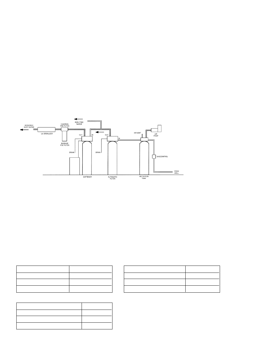
Figure 11