Hydrotech AP1 (115V) Air Pump & Retention Tank Kit User Manual
Page 3
2
SECTION 2: SETTING AND CHECKING HEAD PRESSURE
(Air pump should be assembled before continuing).
Checking Head Pressure:
1.
Loosen lock nut (counter-clockwise) on Air Regulator Valve (ARV).
2.
Now turn adjustment nut counter-clockwise. Back out at least half way. This will relieve the tension on the ball and
spring allowing air to flow freely out the ARV. This will prevent excess pressure from building up when you close off
outlet port.
DO NOT LET PSI EXCEED 75 PSI.
3.
Plug Air Pump into appropriate voltage outlet.
4.
Slowly close off outlet port; completed in Section 1, #5.
5.
Air should be free flowing from ARV and the pressure gauge reading should be zero. If not, continue to turn
adjustment nut counter-clockwise to release pressure.
6.
With Air Pump on, outlet port completely closed and pressure gauge reading at 0 psi, air should be flowing from ARV.
7.
You are now ready to test the ability of the Air ARV at a desired pressure (explained at the end of this section).
8.
To build up head pressure, gradually rotate clockwise the adjustment nut of the ARV. The pressure will begin to rise
as you increase the tension on the ball and spring. Do not exceed 75 psi.
9.
When the desired pressure is reached and air is releasing out the ARV, the Air Pump is set at the proper head
pressure to introduce air into the water line pressure.
10. Do not set ARV above 75 psi because this could cause the standard water pressure relief valve (usually located on
pressure tank) to possibly discharge water in the event of excess pressure build up.
To set and secure ARV setting:
1.
Use adjustment nut to select desired pressure, then thread lock nut clockwise and secure it against the ARV body.
Snug lock nut with wrench. This will lock adjustment at the desired pressure setting.
2.
If pressure does not build while turning in adjustment nut, check the 3 ports on the outlet side of the Air Pump for
leaks (Pressure Gauge, ARV, and Outlet Port). If there are no leaks, the Air Pump may be damaged or seals worn
to the point where no head psi can be created (Repair Kits are available - Item #K767). The Air Pump may run but
no head pressure will be created.
3.
When pressure build up to the desired pressure and ARV is secure, the Air Pump is now ready to install.
4.
See Section 8 for fine adjustments of the ARV.
SECTION 1: ASSEMBLING AIR PUMP
1.
Use teflon tape on male thread connections. Do not over-tighten fittings. Over-tightening can cause pump head to
crack.
2.
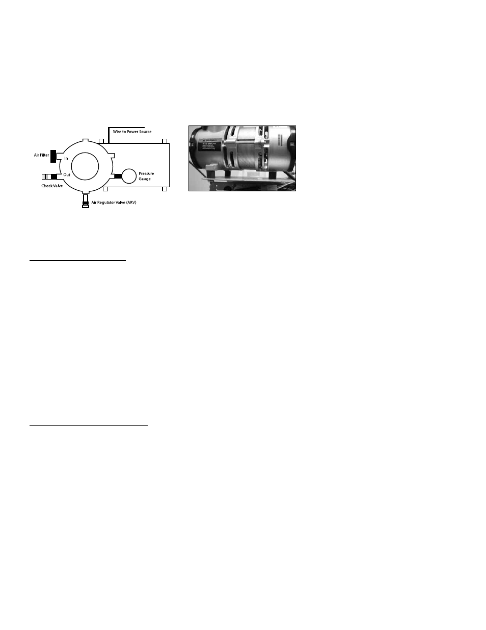
Remove side plug and back plug on outlet side of pump. Use a 1/4” allen wrench or channel locks. See Figure 2.
3.
Install pressure gauge in back port (opposite outlet). See Figure 2.
4.
Install Air Regulator Valve (ARV) into side port. See Figure 2.
5.
Install side 1/4” plug into outlet port (check valve port). See Figure 2.
6.
Thread the three rubber feet into base of pump. See Figure 3.
Figure 2 - Top View
Figure 3