Initial injector setup, Nozzle setup, Optional for maximized optimization) – Hydra-Flex Aqua-Lab MD Operating Manual User Manual
Page 6
Operating Manual
© Hydra-Flex Inc 2011
- 6 -
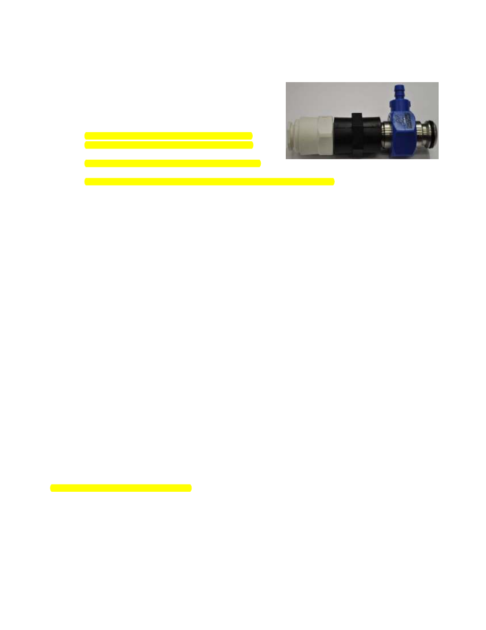
Initial Injector Setup
(Based on field experience this is HFI’s recommended staring point)
1. Using the recommended starting point (appendix page 10) or
the target flow rate and the chemical dilutions chart (appendix)
install the appropriate injector into each port
2. Connect pre-run solution lines to each Injector with the
supplied coupler and push connect fitting
a. Be sure to use teflon tape when connecting the
injector to the coupler and push connect fitting to
ensure there are no leaks
b. Do not over tighten poly fittings or they may crack
3. Connect ¼” poly lines from each chemical container to the appropriate injector
a. Ensure a foot valve or similar check valve/filter is installed on each line
i. These must be present or metering tips may clog
4. Metering tips will need to be installed to set dilution ratio (see appendix for ratio charts to determine tip)
If the spray nozzles on the arch are too small for the injector chosen, the back pressure put on the injector may
cause the vacuum not to function and chemical will not be pulled. The back pressure should not exceed 66 psi.
Back pressure gauges are available for purchase from HFI. (P/N 1001105) Water will continue to flow as normal.
Injector Vacuum Check (for troubleshooting injectors)
1. At the ChemFlex injector, remove the chemical feed line from the injector hose barb.
2. Attach the tubing of the vacuum gauge to the ChemFlex hose barb
3. With the pump(s) on, manually activate the chemical that is to be tested at the main car wash control cabinet. An
injector that is working properly will have a reading greater than or equal to (≥) 20 in Hg
4. If injector is not functioning:
a) Check metering tip for clogs (can be tested with no metering tip to ensure injector is performing)
b) Try smaller injector (this will produce less flow and thus less backpressure)
c) Remove a nozzle(s) at the arch, allowing water to free flow (this will reduce backpressure)
5. Repeat steps 2-4 for each chemical lane that a vacuum reading is needed for.
6. Once testing is complete, turn off the AQUA-LAB pump from the main car wash control cabinet.
There is a variation of performance in the injectors that comes from slight variations in the dimensions of the parts and in assembly that are
unavoidable. It is common to see the resultant vacuum range from 20 in Hg all the way up to 28. There is also variation in the through hole size on the
meter tips from Dema (within their manufacturing tolerances). Using the same tip color from site to site is a good starting point. However with the
potential for variation from part to part it is reasonable to still need to do some adjustments from there.
Nozzle Setup
(optional for maximized optimization)
• Using the recommended starting point (appendix) install the recommended nozzles
o
This may involve removing and plugging some ports
o
Due to the lower water usage determined by the injector of the AQUA-LAB you will need to match the
flow of the application device to the injector
o
Setup the nozzle spray patterns to “paint” the car - slightly overlapping each other