Hellwig Sway Bar 7868 User Manual
Page 4
13
14
15
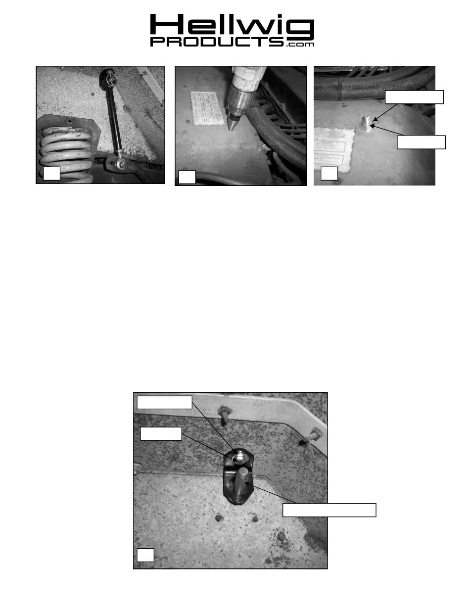
15. Disconnect the end link from the quick disconnect pin and rotate the bar and end link so the end link is against the inside wheel
well. See PHOTO 13.
16. Connect the end link quick disconnect pins to the end link fender tab in the same manner used for the end link lower mounting
bracket.
17. Align tab for best fit and mark where to drill the hole.
BEFORE DRILLING, DISCONNECT BATTERY AND VERIFY
THAT DRILL WILL NOT CONTACT OR DAMAGE ANY BRAKE, FUEL, COOLANT LINES,BATTERY, ELEC-
TRICAL COMPONENETS, WIRING, OR ANY OTHER ENGINE COMPARTMENT COMPONENTS.
18. Drill a 5/16” (.3125”) hole and bolt the end link fender tab to the inner fender. See PHOTOS 14, 15 & 16. The end links can be
disconnected from the axle and moved to these locations when the vehicle is being used offroad and needs additional suspen-
sion flex. For onroad use, leave the end link attached to the lower end link mounting bracket.
19. With the end link attached to the end link fender tab as well as the axle,
bounce the vehicle checking for clearance on all
under carriage components: fuel tank, shocks, differential, brake and fuel lines, etc. Test drive the vehicle and recheck all
clearances and the installation alignment. Adjust as needed. Re-check your installation after one week of driving and periodi-
cally on a regular basis.
20.
The sway bars arms have three mounting holes. Mounting the sway bar on the outer hole (rear-most) is the nominal
position. For a firmer setting, use the inner holes. We recommend starting with the outer mounting hole until you are
accustomed to the vehicles new handling characteristics. Select the mounting point that best fits your driving style.
ATTENTION INSTALLER:
BE SURE THAT THE CUSTOMER RECEIVES THIS INSTRUCTION
SHEET, ALL IMORTANT NOTE CARDS AND THE WARRANTY FORM
559-734-7451 800-367-5480 FAX 559-734-7460
7868 (R-7868)
07/13/2011
16
3/8” Bolt
Quick Disconnect Pin
Stover Nut
Flat Washer
Flat Washer