Hellwig Sway Bar 6908 User Manual
Page 2
TORQUE TABLE
Bolt Size 3/8”— 35 ft lbs * Bolt Size 7/16”— 45 ft lbs* Bolt Size 1/2”—75 ft lbs *Bolt Size 9/16”— 90 ft lbs
SAFETY: BEFORE BEGINNING INSTALLATION BE SURE TO SET THE PARKING BRAKE AND
CHOCK THE WHEELS.
NOTE: TO EASE INSTALLATION AND PROPERLY ADJUST THE BAR, THE WEIGHT OF THE VEHI-
CLE MUST BE ON THE SUSPENSION AS IF DRIVING DOWN THE ROAD. DO NOT RAISE THE VEHI-
CLE BY THE FRAME.
NOTE: THIS KIT REQUIRES DRILLING THE FRAME RAIL AND POSSIBLE RELOCATION OF FUEL
AND BRAKE LINES. INSTALLER MUST ENSURE THAT THE SWAY BAR KIT WILL NOT INTER-
FERE WITH ANY FUEL OR BRAKE LINES OR HOSES.
IMPORTANT NOTE: SWAY BAR END LINKS MUST BE ATTACHED ON OUTER
HOLE PRIOR TO INITIAL USE. SEE PHOTO 11.
1. Lubricate the D shaped bushings and place them onto the straight areas of the bar on each side of the
center hump as close to the outside bend as possible.
2. Remove the breather vent bolt from axle. Place spacer washer under brake line tee and re attach vent
bolt as shown in PHOTO 2. This will provide adequate room for the axle u-bolts to be placed under the
brake lines.
3. Hold bar up to the axle and locate the position on the axle tubes to mount the u-bolts. Orient sway bar
so that the center hump points down.
Be sure to put the U-Bolts Under Any Brake Lines, Wires or
Hoses on the Axle to Avoid Any Possible Damage. The threads of the U-Bolts will point down. See
PHOTO 3.
559-734-7451 800-367-5480 FAX 559-734-7460
5
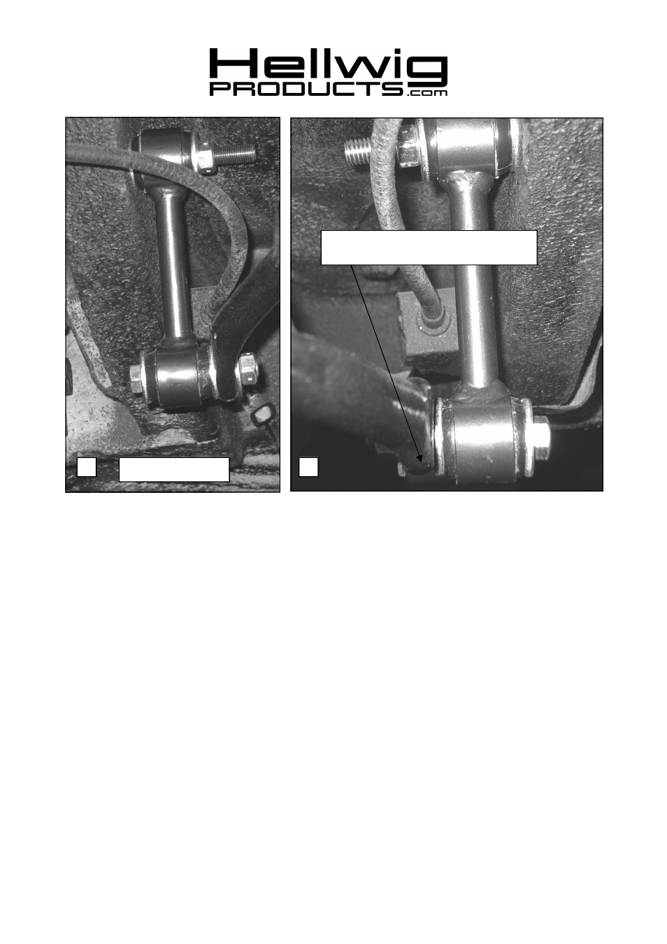
Bottom of sway bar arm to be even with bot-
tom of subframe.
4
Driver’s Side shown
6908 (R-6908)
04/17/07