Hellwig Sway Bar 55905 User Manual
Page 2
559-734-7451 800-367-5480 FAX 559-734-7460
1. If equipped, remove the factory installed anti sway bar and the mounting hardware.
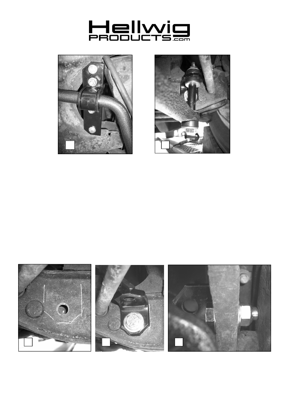
2. Insert bar through hole in K-member as shown in photo 1.
3. Attach mounting plates to K-member as shown in photos 1 & 2 using 3/8-16 X 1-1/4” bolts, large
washers and locknuts. Torque to 25 ft-lb.
4. Lubricate polyurethane D-bushings and install on sway bar in the location where they will attach to
the mounting plates. Place u-plates over D-bushings and attach to mounting plates with 3/8-16 X1-
1/4” bolts, small washers and locknuts. Leave loose for adjustment later.
5. If not equipped with factory sway bar mounts, assemble end links and angle brackets as shown in
photo 3. If equipped with factory sway bar mounts, skip to line 8.
6. Align end links for best alignment and mark location of bracket as shown in photo 4
. Drill a
17/32” (.531) hole in front face of control arm only. Do not drill through rear face of control
arm. See photos 4,5&6.
7. Attach angle bracket to control arm using 1/2” bolt, washers, and locknut as shown in photos 5&6.
Align bracket and torque bolt to 50-60 ft-lb. See photos 5&6.
4
5
2
3
6
5905 ( R-5905 )
04/02/2008