Autostart AS-1412 User Manual
Page 5
AS-1412 Installation Guide
P. 5
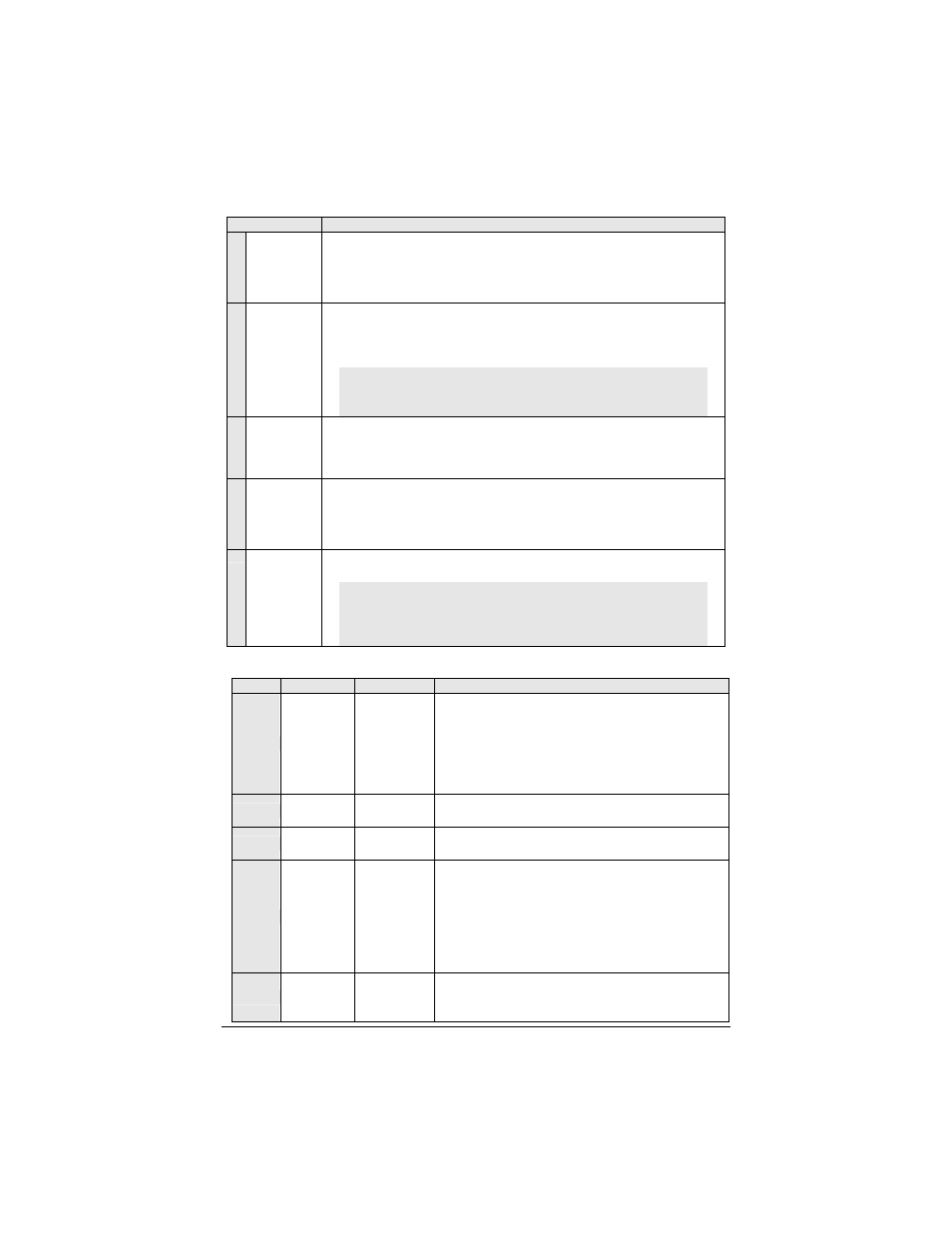
5-Pin Secondary Harness
Wire
Description
1
BLACK
(–) Chassis
ground
input
This wire must be connected to bare, unpainted metal (the Chassis or true
Body ground). It is preferable to use a factory ground bolt rather than a self-
tapping screw. Screws tend to get loose or rusted over time and can
cause erratic problems.
2
PURPLE
(AC)
Tachometer
input
This wire tells the Module if the Engine is running or not. It requires at least
1.8 volts (AC) and 1.5 Hz (or faster) at idle. Common Tach references are:
the negative side of an injector, the negative side of an Ignition Coil,
Camshaft sensor, Crankshaft sensor or the Engine Control Module (ECM).
NOTE: A Tach signal that is too low will cause the Module to “over
crank” and a Tach signal that is too high will cause the Module to
“under crank”.
3
GREY
(-) Hood
Switch
input
Connect this wire to the Hood Pin-switch supplied. This input will disable or
shut down the Remote Starter when the Hood is opened. It is also used for
programming and therefore it is essential that it is installed.
4
ORANGE
(+) Brake
Switch
input
This wire must be connected to the Brake Light switch of the vehicle. The
wire should be +12 V only while the Brake Pedal is pressed. This input will
shut down the Remote Starter if the Brake Pedal is pressed. It is also used
for programming and therefore it is essential that it is installed.
5
YELLOW
+12 V
Parking
Light
output
This wire provides a +12 V output (15 A max.) and must be connected to
the Parking Light wire that tests +12 V when the Parking lights are
ON
.
Note: Ensure that the voltage does not vary when the dimmer control
switch is turned up or down. If this is the case, it is not the right wire.
There is a also a negative Parking Light output. Only one of these
two different outputs needs to be connected.
12-Pin Accessories Harness
Wire
Color
Function
Description
1
BLUE
(–) AUX 3
(
Trunk
) output
500 mA negative output. This output can be used to
control Trunk release (1-sec. pulse) or can be set to
operate as a constant output as long as buttons
, ,,
are held pressed. (For Sunroof or Window close).
AUX3
(
TRUNK)
operates only when Ignition is
OFF
or
when the vehicle is running under remote control.
2
BROWN
(–) Lock output
Programmable 500 mA negative output: 7/10-sec. or 4-
sec. pulse.
3
GREEN
(–) Unlock
output
Programmable 500 mA negative output: 7/10-sec., 4-
sec. or double 1/4-sec. pulse.
4
WHITE /
BROWN
(–) Arm output
Max. 500-mA ground signal when the Doors are locked
by remote. This wire will go to ground 1/4 sec. before
the
LOCK
pulse and go off 1/8 sec. after
LOCK
. It must
be connected to the OEM Arm wire (usually the Door
Pin).
Note: The system also gives a Rearm pulse on this
wire after remote-start shutdown.
5
WHITE /
GREEN
(–) Disarm
output
Max. 500-mA 1-sec. ground pulse when the Doors are
unlocked by remote control. Connect to the OEM
Disarm wire of the vehicle.