Brooks, Model 5860e – Brooks Instrument 5860E User Manual
Page 13
2-3
Installation and Operation Manual
X-TMF-5860E-MFM-eng
Part Number: 541B106AAG
November, 2008
Brooks
®
Model 5860E
Section 2 Installation
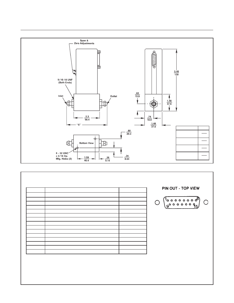
Figure 2-1 Model 5860E Dimensions
Connection
"X" Dim.
1/4" Compression
4.32
Fitting
109.7
1/4" Tube VCO
3.86
98.0
1/4" Tube VCR
4.18
106.2
3/8" Compression
4.44
Fitting
112.8
Figure 2-2 "D" Type Connector Pin Arrangement
PIN NO.
FUNCTION
COLOR CODE
1
Cmd. Common (Command Pot "CCW") •
Black
2
0-5 Volt Signal Output
White
3
Supply Common
Red
4
Valve Off •
Green
5
+15 Vdc Supply
Orange
6
-15 Vdc Supply
Blue
7
Valve Test Point/Purge •
Wht/Blk
8
Cmd. Input or Cmd. Pot "S" •
Red/Blk
9
Supply Voltage Common
Grn/Blk
10
0-5 Volt Signal Common
Org/Blk
11
+5 Volt Reference Output (Command Pot "CW") •
Blu/Blk
12
Valve Override •
Blk/Wht
13
Not Used
Red/Wht
14
Chassis Ground
Grn/Wht
15
Remote Transducer Input* •
Blu/Wht
* Factory Activated Option.
• These connections are used for the 5850E and 5851E Mass Flow Controllers.
Make no connections to these pins.
NOTE:
1. Cable shield tied to chassis ground in
meter connector. Make no connection
on customer end.
2. All power leads must be connected to
power supply.
INCHES/MILLIMETERS