Ips122 series – Brooks Instrument IPS122 2 Indicating Pressure Switches" User Manual
Page 15
Installation and Operation Manual
X-PR-IPS122-eng
Part Number 541B150AAG
January, 2011
IPS122 Series
2-5
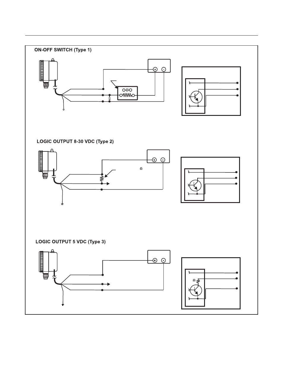
Section 2 Installation
Note: Maximum load = 12 watts
(Volts x Amps = Watts)
Pigtail
Leads
Braided
Shield and
Drain Wire
Load: Relay, Light
or Device
Reference to Internal
NPN Transistor Switch
Red ( + 8 - 30 VDC)
Black (Load)
Green (-Common)
IPS-122
WARNING: DO NOT connect the black control wire directly to the
+ Red power supply wire without a resistive load between them.
MINIMUM value at 12 VDC = 12 ohms, and at 24 VDC = 48 ohms.
Black (Load)
Red (+ 8 - 30 VDC)
Power Supply
8 - 30 VDC
Green (-Common)
Note: Operates logic devices
to a maximum sink of 60 mA.
Power Supply
8 - 30 VDC*
Pigtail
Leads
Red (+ 8 - 30 VDC)
Black (Logic Out)
Green (-Common)
User provided 3K
pull up resistor
Logic Out: (high level = power supply VDC
8-30 VDC (high level) setpoint exceeded
0.1 VDC normal
WARNING : DO NOT connect the black control wire directly to the
+ Red power supply wire without a pull resistor between them.
Braided
Shield and
Drain Wire
Reference to Internal
NPN Transistor Switch
Red (+ 8 - 30 VDC)
Black (Logic Out)
Green (-Common)
IPS-122
Pigtail
Leads
Red (+ 5 VDC)
Black (Logic Out)
Green (-Common)
Braided
Shield and
Drain Wire
Power Supply
+ 5 VDC
4.8 to 5.2 VDC, 5 VDC recommended
at 10.2 mA plus current required by
logic device (up to 60 mA)
*Logic Out:
+ 5 VDC setpoint exceeded,
0 VDC normal
*Note: Operates logic devices to
a maximum sink of 60 mA
NPN Transistor Switch
Red (+ 5 VDC)
Black (Logic Out)
Green (-Common)
IPS-122
Reference to Internal
2K
Figure 2-2 IPS122 Wiring Diagrams