Biamp GPIO-1 User Manual
Page 7
7
GPIO-1 SETUP AND USE
Output Connectors
Sixteen parallel outputs are provided on the GPIO-1 as well as Isolated and Chassis Ground connections. Each output is able to accept
either an external positive voltage between 4 and 30V or use the 24V DC 100mA reference voltage provided on the unit. The 24V DC
supply for use with the Aux Power port is not provided with the unit and will need to be sourced locally. Outputs will be monitored for short
to ground, short to supply and if High Range - Monitored is being used, open circuit conditions will be monitored as well. Consideration
should be given to the state of the output when network connectivity is lost. A Voltage Monitor (VM) input is provided in order that a short
to supply reference voltage is incorporated in output Fault monitoring. A voltage of between 4 - 30V is required by the VM input in order for
the outputs to operate.
If the GPIO-1 Outputs are using a High Range Monitored type of circuit the VM input must match or be greater than the highest Output
Voltage being used. If a higher Voltage is seen on the Outputs compared to the VM Input a Short to Supply fault will be indicated.
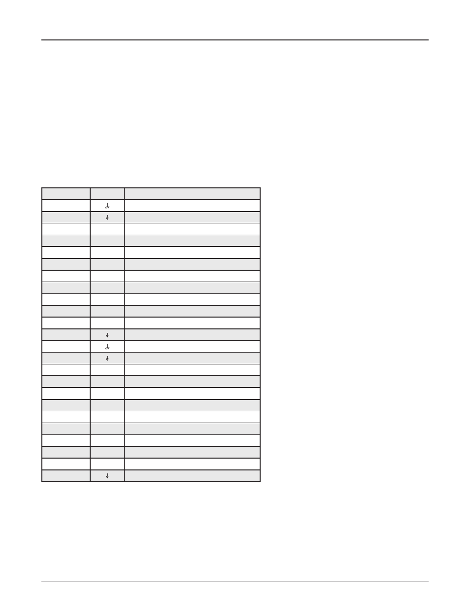
Pin
Label
Function
1
Ground
2
Isolated Ground
3
1
Output 1
4
2
Output 2
5
3
Output 3
6
4
Output 4
7
5
Output 5
8
6
Output 6
9
7
Output 7
10
8
Output 8
11
9
Output 9
12
Isolated Ground
13
Ground
14
Isolated Ground
15
10
Output 10
16
11
Output 11
17
12
Output 12
18
13
Output 13
19
14
Output 14
20
15
Output 15
21
16
Output 16
22
VM
Voltage Monitor*
23
24V DC 24V DC (100mA limited)
24
Isolated Ground
* The VM Input must always be connected to the 24V supply on Pin 23 or if an external
supply is used the supply voltage should be connected to the VM input.