Biamp GPIO-1 User Manual
Page 6
6
GPIO-1 SETUP AND USE
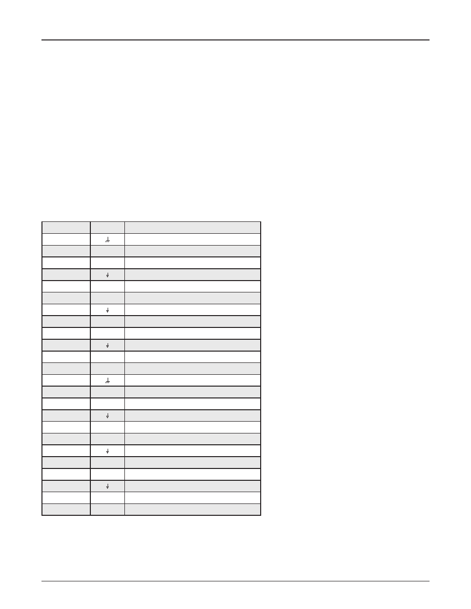
Input Connectors
Sixteen parallel input connections are provided on the GPIO-1 as well as Isolated Ground and Ground connections. Under software control
the logic level of each input can be set independently to operate one of three ways.
• TTL: 2V to 5V logic sense. To enable a TTL input, apply a TTL logic high or low with respect to Isolated Ground. This can be
configured in software to detect a low to high or high to low transition.
• High Range: To enable a High Range input, use a dry contact to switch the input to a voltage of 24V DC with respect to Isolated
Ground. This can be configured in software to detect a low to high or high to low transition.
• High Range – Monitored: This circuit is implemented in the same way as the High Range input. This option allows monitoring of each
input for short to ground and open circuit. In order to sense open circuit, a terminating resistor must be fitted between each Input and
Isolated Ground at the far end of the circuit being sensed. The Inputs will sense open circuits on the line between its input and the
terminating resistor. Shorts to Isolated Ground are sensed across the entire line being monitored. A 6k8Ω resistor should be used for
each input. If a monitoring fault is detected on any input the logic state or transitions on that input will be ignored until the fault is cleared.
High Range – Monitored inputs require a low to high transition to enable the input (transition direction not configurable).
Pin
Label
Function
1
Ground
2
1
Input 1
3
2
Input 2
4
Isolated Ground
5
3
Input 3
6
4
Input 4
7
Isolated Ground
8
5
Input 5
9
6
Input 6
10
Isolated Ground
11
7
Input 7
12
8
Input 8
13
Ground
14
9
Input 9
15
10
Input 10
16
Isolated Ground
17
11
Input 11
18
12
Input 12
19
Isolated Ground
20
13
Input 13
21
14
Input 14
22
Isolated Ground
23
15
Input 15
24
16
Input 16