Installation application examples – Flowline LC1X Compact Controller User Manual
Page 5
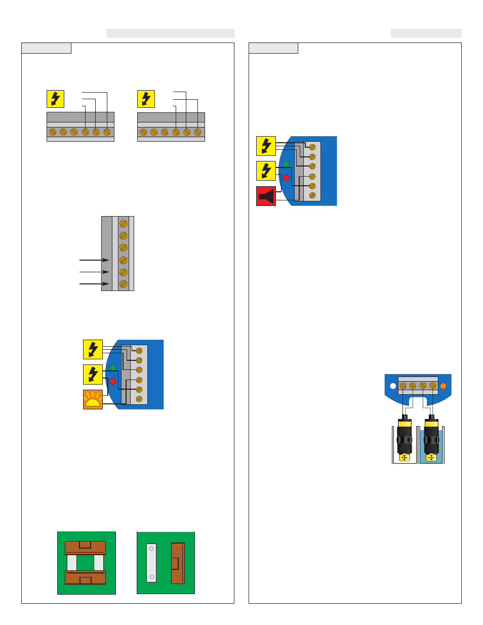
VAC Power Input Wiring:
Observe the labeling on the LC10/LC11. Note: Polarity does not mat-
ter with the AC input terminal.
Step Six
Step Seven
INSTALLATION
APPLICATION EXAMPLES
Relay Input Wiring
The relay is a single pole, double throw type rated at 250 Volts AC,
10 Amps, 1/4 Hp. The two terminal NO and NC (normally open and
normally closed) will be used in different applications. Remember
that the "normal" state is when the relay coil is de-energized and the
Red relay LED is Off / de-energized.
Strobe Alert Output
With the Strobe Alert wired NC, it can be used as a high or low level
alarm, depending on the setting for the invert switch. Strobe can also
be wired NO.
Changing from 120 to 240 VAC
1. Remove the two screws from the top of the printed circuit board
(PCB) and gently slide the PCB from the housing. Use caution when
removing the PCB.
2. Located jumpers JWA, JWB and JWC on the PCB.
3. To change to 240 VAC, remove jumpers from JWB and JWC and
place a single jumper across JWA. To change to 120 VAC, remove
jumper JWA and place jumpers across JWB and JWC.
4. Gently return PCB into housing and replace the two screws.
120 VAC
240 VAC
Configuration
Configuration
Low Level Alarm
The goal is to make sure that the liquid level does not fall below a cer-
tain point. If it does, an alarm is supposed to sound, alerting the oper-
ator of a low level condition.
If power is accidentally cut to the controller, the sensor's ability to
notify the operator of a low level condition could be lost. The system
must alert the operator not only to low liquid level, but to controller
power loss.
To do this, connect the hot lead of the
alarm to the NC side of the relay ter-
minal of the controller. If power is
lost, the relay will be de-energized,
and the alarm will sound (if there is
still power to the alarm circuit itself).
The alarm circuit should have a non-
interruptible power supply or some
other indicator or backup alarm to
warn of a power failure in the alarm circuit.
In this application, the normal status if the sensor at the bottom if the
tank will be wet, and the relay will be energized holding the alarm cir-
cuit open. Both the relay LED and the Input LED will be on simulta-
neously, so for this application, Invert should be set to the Off position.
High Level Alarm
In the same manor, this system can be used to sound an alarm when
fluid reaches a high level, with just a change in the location of the sen-
sor and the setting of the Invert switch.
The alarm is still connected to the NC side of the relay to allow for a
power failure alarm.
The sensor is normally dry. In this condition, we want the relay to be
energized so the alarm does not sound: i.e., the Red relay LED should
be on whenever the Input LED is Amber. So we turn Invert On. If the
fluid level rises to the high sensor point, the sensor goes on, the relay
de-energizes, and the alarm sounds.
LED Indication:
Use LED's located above the input terminals
to indicate whether the switch is in a wet or
dry state. With powered switches, Green
indicates dry and Amber indicates wet. With
reed switches, Amber indicates wet and no
LED indicates dry. Note: reed switches may
be wired in reverse so that wet indicates dry
and Amber indicates dry.
JWB
JWC
JW
A
JWB
JWC
JW
A
AC
AC
GND
NC
C
NO
R
P
AC
AC
GND
NC
C
NO
R
P
Strobe
HOT
NRTL
GND
AC
AC
GN
NC
C
N
O
AC
AC
GND
NC
C
NO
HOT
NRTL
GND
AC
AC
G
N
N
C
C
N
O
Relay
T
erminals
1B
1A
(-) (+)
(-) (+)
Off
Amber
(-) (+)