Wiring, Maintenance, Vac power input wiring – Flowline AX1X Thermo-Flo User Manual
Page 6: Relay input wiring, Strobe alert output, General, Cleaning procedure, Testing the flow switch
Step Eight
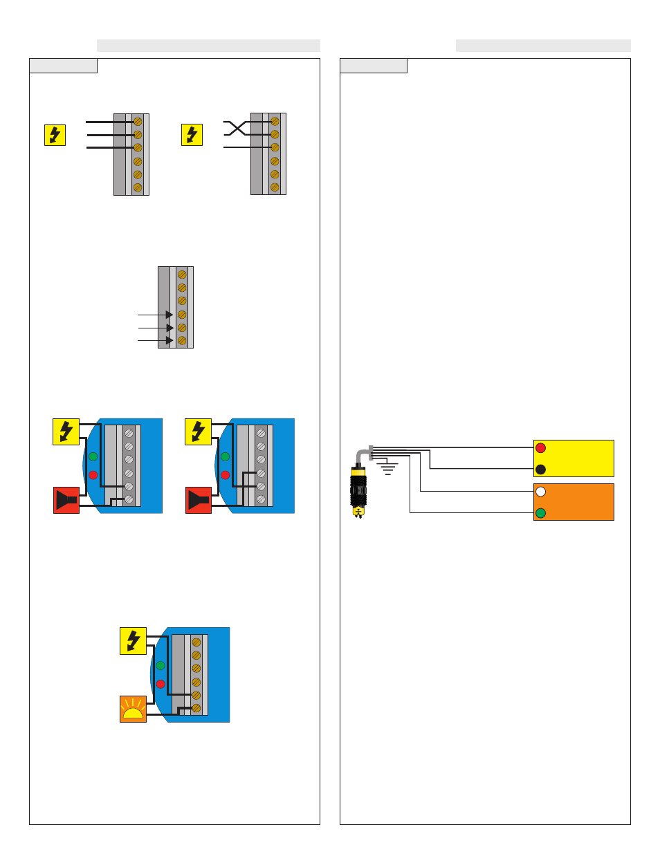
VAC Power Input Wiring:
Observe the labeling on the con-
troller. Note: Polarity does not matter with the AC input terminal.
Relay Input Wiring:
The relay is a single pole, double throw
type rated at 250 Volts AC, 10 Amps. The terminals Normally Open
(NO) and Normally Closed (NC) will be used in different applica-
tions. Remember that the "normal" state is when the relay coil is de-
energized and the Red relay LED is OFF (de-energized).
A typical application for the Switch Pro™ with Compact Relay
Controller is to operate a pump or valve between the two set points
(automatic fill or empty). In this application, a pump or valve can be
wired to either the Normally Open (NO) or Normally Closed (NC)
side of the relay.
AC
AC
GND
NC
C
NO
R
P
Strobe
HOT
NRTL
GND
AC
AC
GND
NC
C
NO
AC
AC
GND
NC
C
NO
HOT
NRTL
GND
AC
AC
GND
NC
C
NO
Relay
Terminals
Strobe Alert Output
With the Strobe Alert wired NO, the strobe will flash when the Red
LED is ON (Invert OFF). The strobe will flash when the Red LED is
OFF when wired NC or by turning the Invert ON. If the strobe is
wired NC and the Invert is ON, the strobe will flash when the Red
LED is ON (same as NO wiring and Invert OFF).
AC
AC
AC
AC
GND
GND
NC
NC
C
C
NO
NO
R
R
P
P
Alarm
AC
AC
AC
AC
GND
GND
NC
NC
C
C
NO
NO
R
R
P
P
Alarm
NO Wiring
NC Wiring
Power to
Switch Pro
not shown.
Power to
Switch Pro
not shown.
Power to
Switch Pro
not shown.
WIRING
Step Nine
MAINTENANCE
General:
The Switch-Pro™ flow switch requires no periodic
maintenance except to clean off any deposits or scaling from the sen-
sor tip as necessary. It is the responsibility of the user to determine
the appropriate maintenance schedule, based on the specific charac-
teristics of the application liquids.
Cleaning Procedure:
1. Power:
Make Sure that all power to the sensor, controller and/or
power supply is completely disconnected.
2. Sensor Removal:
Make sure that the flow is off and the pres-
sure is down prior to removing the Switch-Pro™. Carefully, remove
the sensor from the installation. Replace the sensor with a 3/4” NPT
plug to insure that liquid does not leak out during this procedure. Do
not re-install the Switch-Pro™ if the threads are damaged.
3. Cleaning the Sensor:
Use a soft bristle brush and mild deter-
gent, carefully wash the Switch-Pro™ flow switch. Do not use
harsh abrasives such as steel wool or sandpaper, which might
damage the surface sensor. Do not use incompatible solvents
which may damage the sensor's PP/Ryton or PVDF plastic body.
4. Sensor Installation:
Follow the appropriate steps of installa-
tion as outlined in the installation section of this manual.
Testing the Flow Switch:
Used to verify if the sensor is indicating a no-flow or flow condition.
This test uses all four-wires (Red, Black, White and Green). With Red
to Positive and Black to Negative, the Contacts (White and Green) will
be Open in a Flow Condition and Closed in a No-Flow Condition.
Also, the Red LED in the switch will ne OFF for a Flow Condition and
ON for a No-Flow Condition.
Red
Black
Shield
Ground
24 VDC
Power Supply
+
-
Multimeter
(Continuity)
-
+
White
Green